Samoan
- Afrikaans
- Albanian
- Amharic
- Arabic
- Armenian
- Azerbaijani
- Basque
- Belarusian
- Bengali
- Bosnian
- Bulgarian
- Catalan
- Cebuano
- Corsican
- Croatian
- Czech
- Danish
- Dutch
- English
- Esperanto
- Estonian
- Finnish
- French
- Frisian
- Galician
- Georgian
- German
- Greek
- Gujarati
- Haitian Creole
- hausa
- hawaiian
- Hebrew
- Hindi
- Miao
- Hungarian
- Icelandic
- igbo
- Indonesian
- irish
- Italian
- Japanese
- Javanese
- Kannada
- kazakh
- Khmer
- Rwandese
- Korean
- Kurdish
- Kyrgyz
- Lao
- Latin
- Latvian
- Lithuanian
- Luxembourgish
- Macedonian
- Malgashi
- Malay
- Malayalam
- Maltese
- Maori
- Marathi
- Mongolian
- Myanmar
- Nepali
- Norwegian
- Norwegian
- Occitan
- Pashto
- Persian
- Polish
- Portuguese
- Punjabi
- Romanian
- Russian
- Samoan
- Scottish Gaelic
- Serbian
- Sesotho
- Shona
- Sindhi
- Sinhala
- Slovak
- Slovenian
- Somali
- Spanish
- Sundanese
- Swahili
- Swedish
- Tagalog
- Tajik
- Tamil
- Tatar
- Telugu
- Thai
- Turkish
- Turkmen
- Ukrainian
- Urdu
- Uighur
- Uzbek
- Vietnamese
- Welsh
- Bantu
- Yiddish
- Yoruba
- Zulu
Telephone: +86 13120555503
Email: frank@cypump.com
Nov . 14, 2024 16:00 Back to list
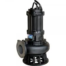
slurry pump diagram
Understanding the Slurry Pump Diagram
Slurry pumps play a crucial role in various industries, particularly in the mining, construction, and waste management sectors. They are designed to handle the transportation of materials that are usually mixtures of solid and liquid, commonly referred to as slurry. To grasp the functionality and components of a slurry pump, examining a slurry pump diagram can provide invaluable insights.
Components of a Slurry Pump
A typical slurry pump diagram illustrates several key components essential for the efficient operation of the pump
.1. Pump Casing This is the outer shell of the pump that houses the internal components. Made from durable materials, the casing is designed to withstand the abrasive nature of the slurry. It is usually lined with materials such as rubber or metal to resist wear.
2. Impeller The heart of the pump, the impeller is a rotating component that creates the hydraulic energy required to move the slurry. Its design is crucial, as it must effectively handle both the liquid and solid particles without causing significant wear.
3. Suction and Discharge Ports These openings allow the slurry to enter and exit the pump. The suction port draws slurry into the pump, while the discharge port releases it into the designated pipeline or receptacle.
4. Drive Shaft The pump is powered by a motor connected to a drive shaft, which transmits torque to the impeller. The design of the shaft is important, as it must be robust enough to handle the operational stresses.
5. Seals To prevent leakage and maintain efficiency, seals are used to ensure that the slurry does not escape from the pump casing. This is especially critical in slurry pumps, as any leakage can lead to severe operational issues.
6. Bearing Bearings support the rotating components and help reduce friction. They are often designed to withstand extreme conditions typical in slurry pumping applications.
slurry pump diagram

Working Principles
The operation of a slurry pump can be broken down into several stages as depicted in the diagram. When the pump is activated, the impeller begins to rotate, creating a vacuum at the suction port. This vacuum draws the slurry into the pump casing. As the slurry enters, it is subjected to centrifugal force generated by the rotating impeller, which propels it toward the discharge port.
The design of the impeller and casing facilitates the efficient transfer of energy from the motor to the slurry. The mixture of liquid and solids is transported through pipes to its destination, where it can be processed or disposed of.
Importance of Slurry Pump Diagrams
Understanding a slurry pump through its diagram is critical for several reasons
- Maintenance and Troubleshooting Having a visual reference helps engineers and technicians identify components and understand the flow of the slurry, which is essential during maintenance or troubleshooting.
- Design and Customization Engineers can utilize the diagram to design custom slurry pumps tailored to specific applications. Adjustments can be made to components like impeller type, casing material, and size to handle varying characteristics of slurry.
- Training and Safety For new operators, a slurry pump diagram serves as an educational tool. Understanding the components and the operational flow can enhance safety protocols, reducing the risk of accidents.
Conclusion
In summary, slurry pumps are indispensable in industries that require the movement of abrasive mixtures. The slurry pump diagram serves as a comprehensive guide to understanding its components and operational principles. By studying the diagram, professionals can enhance the efficiency, reliability, and safety of slurry pumping operations, ultimately contributing to the success of their respective industries. Whether for optimization, repair, or training purposes, the knowledge derived from a slurry pump diagram is invaluable.
-
Heavy-Duty Mining Sludge Pumps - Wear-Resistant Slurry Handling
NewsAug.02,2025
-
Horizontal Split Case Pump with GPT-4 Turbo | High Efficiency
NewsAug.01,2025
-
ISG Series Pipeline Pump - Chi Yuan Pumps | High Efficiency, Durable Design
NewsAug.01,2025
-
Advanced Flue Gas Desulfurization Pump with GPT-4 Turbo | Durable & Efficient
NewsJul.31,2025
-
ISG Series Vertical Pipeline Pump - Chi Yuan Pumps | Advanced Hydraulic Design&Durable Construction
NewsJul.31,2025
-
ISG Series Vertical Pipeline Pump - Chi Yuan Pumps | Energy Efficient & Low Noise
NewsJul.31,2025


