English
- Afrikaans
- Albanian
- Amharic
- Arabic
- Armenian
- Azerbaijani
- Basque
- Belarusian
- Bengali
- Bosnian
- Bulgarian
- Catalan
- Cebuano
- Corsican
- Croatian
- Czech
- Danish
- Dutch
- English
- Esperanto
- Estonian
- Finnish
- French
- Frisian
- Galician
- Georgian
- German
- Greek
- Gujarati
- Haitian Creole
- hausa
- hawaiian
- Hebrew
- Hindi
- Miao
- Hungarian
- Icelandic
- igbo
- Indonesian
- irish
- Italian
- Japanese
- Javanese
- Kannada
- kazakh
- Khmer
- Rwandese
- Korean
- Kurdish
- Kyrgyz
- Lao
- Latin
- Latvian
- Lithuanian
- Luxembourgish
- Macedonian
- Malgashi
- Malay
- Malayalam
- Maltese
- Maori
- Marathi
- Mongolian
- Myanmar
- Nepali
- Norwegian
- Norwegian
- Occitan
- Pashto
- Persian
- Polish
- Portuguese
- Punjabi
- Romanian
- Russian
- Samoan
- Scottish Gaelic
- Serbian
- Sesotho
- Shona
- Sindhi
- Sinhala
- Slovak
- Slovenian
- Somali
- Spanish
- Sundanese
- Swahili
- Swedish
- Tagalog
- Tajik
- Tamil
- Tatar
- Telugu
- Thai
- Turkish
- Turkmen
- Ukrainian
- Urdu
- Uighur
- Uzbek
- Vietnamese
- Welsh
- Bantu
- Yiddish
- Yoruba
- Zulu
Telephone: +86 13120555503
Email: frank@cypump.com
Sep . 25, 2024 18:57 Back to list
mixed flow pump diagram
Understanding Mixed Flow Pump Diagrams An In-Depth Analysis
Mixed flow pumps are a critical component in various industrial and commercial applications, providing efficient fluid transportation. These pumps function by combining the characteristics of both centrifugal and axial flow pumps, offering a unique solution for applications that require a moderate head with a considerable flow rate. To grasp the workings of mixed flow pumps, one must delve into the intricacies of their design, operational principles, and the significance of their diagrams.
What is a Mixed Flow Pump?
A mixed flow pump operates by propelling fluids at an angle, effectively mixing the principles of axial and centrifugal flow. Unlike centrifugal pumps, which primarily operate based on centrifugal force, mixed flow pumps leverage both radial and axial forces to move the liquid. This combination allows them to handle varying flow conditions efficiently, making them ideal for environments where fluid viscosity and flow requirements fluctuate.
Key Components of Mixed Flow Pumps
The basic structure of a mixed flow pump includes several key components
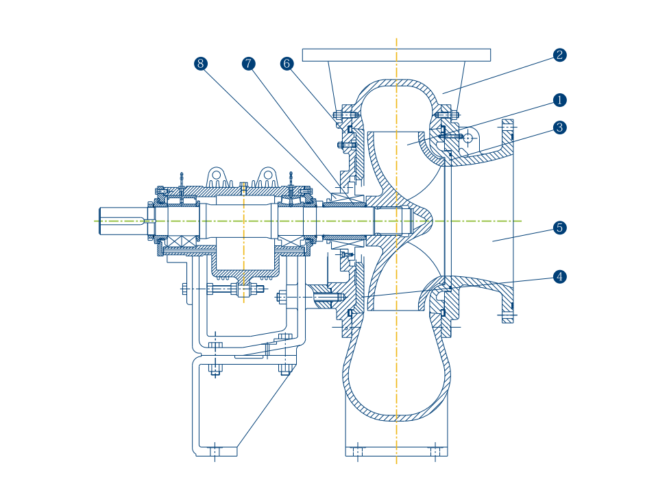
1. Impeller This is the rotating part of the pump that imparts energy to the fluid. In mixed flow pumps, the impeller is designed to create both axial and radial flow. 2. Volute The volute casing collects the fluid that has been accelerated by the impeller and converts its kinetic energy into pressure energy.
3. Suction and Discharge Nozzles These parts allow for the ingress and egress of the fluid, maintaining efficient flow patterns.
4. Bearings These parts hold the rotating shaft and ensure smooth operation, reducing friction and wear.
mixed flow pump diagram

The Mixed Flow Pump Diagram
A mixed flow pump diagram visually represents these components and their interactions. The diagram typically includes labels for each part, showcasing the flow direction, the forces at play, and the arrangement of the impeller and casing. Understanding this diagram is crucial for engineers and technicians, as it serves as a blueprint for both the operation and maintenance of the pump.
The arrow in the diagram often indicates the flow direction, which helps in visualizing how fluid enters and exits the pump. Additionally, the diagram may include annotations on operational parameters such as pressure, flow rate, and energy efficiency which are vital for assessing performance.
Operational Principles
In operation, mixed flow pumps utilize the rotational motion of the impeller to generate kinetic energy in the fluid. As the impeller spins, it creates a low-pressure zone at the inlet, drawing the fluid into the pump. The design of the impeller blades is critical they are angled to facilitate both axial and radial flow. As the fluid moves through the impeller, it gains velocity and moves toward the volute, where its kinetic energy is transformed into pressure energy, resulting in a high-pressure output.
Understanding the pump's performance curve is crucial. This curve illustrates how flow rate varies with the head developed by the pump. It is essential for selecting the right pump for specific applications, ensuring that the system operates within the desired efficiency range.
Applications of Mixed Flow Pumps
Mixed flow pumps find applications across various industries, including water treatment, irrigation, HVAC systems, and chemical processing. Their ability to handle large volumes of fluid at moderate pressures makes them suitable for transferring effluents, stormwater management, and even in cooling towers.
Conclusion
In summary, mixed flow pumps play a significant role in modern fluid dynamics. The mixed flow pump diagram serves as an essential tool for understanding the functionality and design of these pumps. Its components work in harmony to achieve efficient fluid transportation across various applications. For engineers and operators, a thorough understanding of mixed flow pump diagrams is invaluable, paving the way for better design choices, enhanced maintenance strategies, and optimized system performance. As technology advances, the role of mixed flow pumps will likely grow, underscoring the importance of mastering their operational principles and visual representations.
-
Horizontal Split Case Pump with GPT-4 Turbo | High Efficiency
NewsAug.01,2025
-
ISG Series Pipeline Pump - Chi Yuan Pumps | High Efficiency, Durable Design
NewsAug.01,2025
-
Advanced Flue Gas Desulfurization Pump with GPT-4 Turbo | Durable & Efficient
NewsJul.31,2025
-
ISG Series Vertical Pipeline Pump - Chi Yuan Pumps | Advanced Hydraulic Design&Durable Construction
NewsJul.31,2025
-
ISG Series Vertical Pipeline Pump - Chi Yuan Pumps | Energy Efficient & Low Noise
NewsJul.31,2025
-
pipeline pump - Chi Yuan Pumps Co., LTD.|High Efficiency&Low Noise
NewsJul.31,2025


