English
- Afrikaans
- Albanian
- Amharic
- Arabic
- Armenian
- Azerbaijani
- Basque
- Belarusian
- Bengali
- Bosnian
- Bulgarian
- Catalan
- Cebuano
- Corsican
- Croatian
- Czech
- Danish
- Dutch
- English
- Esperanto
- Estonian
- Finnish
- French
- Frisian
- Galician
- Georgian
- German
- Greek
- Gujarati
- Haitian Creole
- hausa
- hawaiian
- Hebrew
- Hindi
- Miao
- Hungarian
- Icelandic
- igbo
- Indonesian
- irish
- Italian
- Japanese
- Javanese
- Kannada
- kazakh
- Khmer
- Rwandese
- Korean
- Kurdish
- Kyrgyz
- Lao
- Latin
- Latvian
- Lithuanian
- Luxembourgish
- Macedonian
- Malgashi
- Malay
- Malayalam
- Maltese
- Maori
- Marathi
- Mongolian
- Myanmar
- Nepali
- Norwegian
- Norwegian
- Occitan
- Pashto
- Persian
- Polish
- Portuguese
- Punjabi
- Romanian
- Russian
- Samoan
- Scottish Gaelic
- Serbian
- Sesotho
- Shona
- Sindhi
- Sinhala
- Slovak
- Slovenian
- Somali
- Spanish
- Sundanese
- Swahili
- Swedish
- Tagalog
- Tajik
- Tamil
- Tatar
- Telugu
- Thai
- Turkish
- Turkmen
- Ukrainian
- Urdu
- Uighur
- Uzbek
- Vietnamese
- Welsh
- Bantu
- Yiddish
- Yoruba
- Zulu
Telephone: +86 13120555503
Email: frank@cypump.com
Dec . 07, 2024 02:49 Back to list
mixed flow pump diagram
Understanding the Mixed Flow Pump Diagram
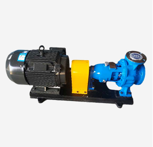
A mixed flow pump is a type of centrifugal pump that combines features of both axial and radial pumps. It is primarily used in applications requiring relatively high flow rates at moderate head pressures. Understanding the mixed flow pump diagram is crucial for engineers and technicians involved in the design, operation, and maintenance of fluid systems.
Basic Components
At the heart of the mixed flow pump are its key components, which are typically depicted in a diagram. The main components include the impeller, volute, casing, and suction and discharge pipes.
1. Impeller The impeller is the rotating part of the pump that imparts kinetic energy to the fluid. In mixed flow pumps, the impeller blades are designed to push the fluid both radially and axially. This dual flow direction is what distinguishes mixed flow pumps from purely axial or radial designs.
2. Volute The volute is a spiral-shaped casing that surrounds the impeller. Its primary function is to convert kinetic energy from the impeller into pressure energy. The shape of the volute is critical for optimizing the pump’s performance and ensuring a smooth flow transition.
3. Casing The casing encloses the impeller and volute, providing structural integrity and preventing leaks. It also includes inlet and outlet openings that facilitate fluid entry and exit.
4. Suction and Discharge Pipes These pipes connect the pump to the fluid system. The suction pipe draws fluid into the pump, while the discharge pipe carries the pressurized fluid away from the pump.
Operating Principle
mixed flow pump diagram

The operation of a mixed flow pump can be understood by analyzing the flow dynamics represented in the diagram. When the impeller rotates, it creates a low-pressure area at the inlet, allowing fluid to enter the pump through the suction pipe. As the impeller blades move the fluid, it gains kinetic energy, which is partially directed radially outward and partially along the axis of the pump.
Once the fluid exits the impeller, it enters the volute. The expanding cross-section of the volute allows the fluid velocity to decrease, which in turn increases pressure. This pressure is then directed through the discharge pipe into the intended system.
Advantages of Mixed Flow Pumps
Mixed flow pumps have several advantages, making them a popular choice for various applications, including irrigation, drainage, and industrial processes
- High Flow Rates Due to their design, mixed flow pumps can handle large volumes of fluid efficiently. - Moderate Head Pressure They are capable of operating effectively at moderate pressure, making them suitable for specific applications that require a balance of flow and pressure.
- Versatility These pumps can be used in a wide range of fluids, including clean water, sewage, and even some chemicals, depending on the materials used in their construction.
Conclusion
The mixed flow pump diagram is a valuable tool for understanding the functionality and application of this type of pump. By studying its components and operating principles, engineers can optimize pump selection and performance for a variety of fluid transfer tasks. Whether used in municipal water systems, agricultural operations, or industrial processes, the mixed flow pump plays a crucial role in ensuring efficient fluid management. Recognizing its benefits and operating characteristics will allow for better design, operation, and maintenance practices, ultimately enhancing the reliability and efficiency of fluid transport systems.
-
ISG Series Vertical Pipeline Pump - Chi Yuan Pumps Co., LTD.|Advanced Hydraulic Design&Energy-Efficient Solutions
NewsJul.30,2025
-
ISG Series Vertical Pipeline Pump - Chi Yuan Pumps Co., LTD.
NewsJul.30,2025
-
ISG Series Vertical Pipeline Pump - Chi Yuan Pumps Co., LTD.|energy-efficient fluid handling&industrial durability
NewsJul.30,2025
-
ISG Series Vertical Pipeline Pump - Chi Yuan Pumps | Advanced Engineering&Industrial Efficiency
NewsJul.30,2025
-
ISG Series Pipeline Pump - Chi Yuan Pumps | High Efficiency, Energy Saving
NewsJul.30,2025
-
ISG Series Vertical Pipeline Pump-Chi Yuan Pumps|High Efficiency&Reliable Performance
NewsJul.29,2025


