English
- Afrikaans
- Albanian
- Amharic
- Arabic
- Armenian
- Azerbaijani
- Basque
- Belarusian
- Bengali
- Bosnian
- Bulgarian
- Catalan
- Cebuano
- Corsican
- Croatian
- Czech
- Danish
- Dutch
- English
- Esperanto
- Estonian
- Finnish
- French
- Frisian
- Galician
- Georgian
- German
- Greek
- Gujarati
- Haitian Creole
- hausa
- hawaiian
- Hebrew
- Hindi
- Miao
- Hungarian
- Icelandic
- igbo
- Indonesian
- irish
- Italian
- Japanese
- Javanese
- Kannada
- kazakh
- Khmer
- Rwandese
- Korean
- Kurdish
- Kyrgyz
- Lao
- Latin
- Latvian
- Lithuanian
- Luxembourgish
- Macedonian
- Malgashi
- Malay
- Malayalam
- Maltese
- Maori
- Marathi
- Mongolian
- Myanmar
- Nepali
- Norwegian
- Norwegian
- Occitan
- Pashto
- Persian
- Polish
- Portuguese
- Punjabi
- Romanian
- Russian
- Samoan
- Scottish Gaelic
- Serbian
- Sesotho
- Shona
- Sindhi
- Sinhala
- Slovak
- Slovenian
- Somali
- Spanish
- Sundanese
- Swahili
- Swedish
- Tagalog
- Tajik
- Tamil
- Tatar
- Telugu
- Thai
- Turkish
- Turkmen
- Ukrainian
- Urdu
- Uighur
- Uzbek
- Vietnamese
- Welsh
- Bantu
- Yiddish
- Yoruba
- Zulu
Telephone: +86 13120555503
Email: frank@cypump.com
Aug . 22, 2024 05:40 Back to list
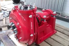
Diagram Illustrating the Components and Operation of a Mixed Flow Pump
Understanding the Mixed Flow Pump Diagram
Mixed flow pumps are an essential component in various industries, traversing a realm of applications from water supply systems to chemical processing. The functionality and efficiency of these pumps can be better appreciated through a detailed understanding of their diagrams, which illustrate the internal design and flow mechanics.
At the core of the mixed flow pump diagram is the impeller, a key element that facilitates fluid movement. The impeller typically consists of several blades that are positioned at an angle, allowing it to impart both kinetic and pressure energy to the fluid. In contrast to centrifugal pumps, which predominantly rely on radial flow, mixed flow pumps utilize a combination of radial and axial flow. This unique characteristic allows them to handle fluids with varying viscosity and specific gravity, making them versatile for different uses.
The mixed flow pump diagram typically depicts the inlet, impeller, volute, and discharge
. The inlet is where the fluid enters the pump, and it’s crucial that the design here minimizes turbulence to ensure smooth flow into the impeller. Once the fluid enters the impeller, it is subjected to the rotating blades, which accelerate the fluid outward. The angle of the blades plays a crucial role in determining how much of the kinetic energy converts to pressure.As the fluid exits the impeller, it enters the volute—a spiral-shaped component designed to convert the high-velocity fluid leaving the impeller into pressure. The volute’s design slows the flow down as it expands, allowing the pump to generate higher pressure. This design is instrumental for applications where maintaining a steady pressure is vital.
mixed flow pump diagram

Understanding the diagram also highlights important features like the wear rings and the casing design. Wear rings, located adjacent to the impeller, are crucial for minimizing leakage between the impeller and the casing. They preserve pump efficiency and enhance the lifespan of the pump by reducing abrasive wear. Moreover, the casing design can vary depending on the intended application; some are designed for high flow rates while others cater to higher pressures.
Additionally, the mixed flow pump diagram often outlines the motor coupling, which connects the motor to the pump. The efficiency of this coupling is critical, as energy losses during this connection can significantly impact overall pump performance.
In terms of applications, mixed flow pumps excel in scenarios where a significant volume of fluid at a moderate pressure is required. They are frequently employed in irrigation, drainage, and municipal water systems. In industrial applications, you’ll find them in processes like wastewater treatment and chemical processing, where reliability and efficiency are paramount.
Furthermore, it’s essential to consider the maintenance aspect, which is often represented in the diagram through various key points. Regular inspections and maintenance protocols are necessary to ensure the longevity and reliability of mixed flow pumps. Understanding the layout of the components as illustrated in the diagram helps technicians carry out necessary checks effectively.
In conclusion, the mixed flow pump diagram serves as an invaluable tool in both understanding and operation. It encapsulates the essence of pump design and functionality, guiding engineers and technicians in optimizing and maintaining these critical machines. Whether in industrial manufacturing or municipal services, the mixed flow pump remains a cornerstone technology for fluid transport, illustrating the importance of design in engineering excellence.
-
ISG Series Vertical Pipeline Pump - Chi Yuan Pumps Co., LTD.|Advanced Hydraulic Design&Energy-Efficient Solutions
NewsJul.30,2025
-
ISG Series Vertical Pipeline Pump - Chi Yuan Pumps Co., LTD.
NewsJul.30,2025
-
ISG Series Vertical Pipeline Pump - Chi Yuan Pumps Co., LTD.|energy-efficient fluid handling&industrial durability
NewsJul.30,2025
-
ISG Series Vertical Pipeline Pump - Chi Yuan Pumps | Advanced Engineering&Industrial Efficiency
NewsJul.30,2025
-
ISG Series Pipeline Pump - Chi Yuan Pumps | High Efficiency, Energy Saving
NewsJul.30,2025
-
ISG Series Vertical Pipeline Pump-Chi Yuan Pumps|High Efficiency&Reliable Performance
NewsJul.29,2025


