TEL:
+86 13120555503
Haitian Creole
- Afrikaans
- Albanian
- Amharic
- Arabic
- Armenian
- Azerbaijani
- Basque
- Belarusian
- Bengali
- Bosnian
- Bulgarian
- Catalan
- Cebuano
- Corsican
- Croatian
- Czech
- Danish
- Dutch
- English
- Esperanto
- Estonian
- Finnish
- French
- Frisian
- Galician
- Georgian
- German
- Greek
- Gujarati
- Haitian Creole
- hausa
- hawaiian
- Hebrew
- Hindi
- Miao
- Hungarian
- Icelandic
- igbo
- Indonesian
- irish
- Italian
- Japanese
- Javanese
- Kannada
- kazakh
- Khmer
- Rwandese
- Korean
- Kurdish
- Kyrgyz
- Lao
- Latin
- Latvian
- Lithuanian
- Luxembourgish
- Macedonian
- Malgashi
- Malay
- Malayalam
- Maltese
- Maori
- Marathi
- Mongolian
- Myanmar
- Nepali
- Norwegian
- Norwegian
- Occitan
- Pashto
- Persian
- Polish
- Portuguese
- Punjabi
- Romanian
- Russian
- Samoan
- Scottish Gaelic
- Serbian
- Sesotho
- Shona
- Sindhi
- Sinhala
- Slovak
- Slovenian
- Somali
- Spanish
- Sundanese
- Swahili
- Swedish
- Tagalog
- Tajik
- Tamil
- Tatar
- Telugu
- Thai
- Turkish
- Turkmen
- Ukrainian
- Urdu
- Uighur
- Uzbek
- Vietnamese
- Welsh
- Bantu
- Yiddish
- Yoruba
- Zulu
Telephone: +86 13120555503
Email: frank@cypump.com
Jan . 14, 2025 11:11 Back to list
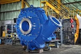
Vertical Slurry Pumps
A slurry pump diagram acts as a valuable resource in the industrial and engineering sectors, serving as an essential guide for the operation, maintenance, and optimization of these vital components in various systems. As someone with a wealth of experience in the industry, I can attest that understanding these diagrams is crucial for ensuring the efficiency and longevity of slurry pumps.
In terms of authoritativeness, manufacturers often provide slurry pump diagrams as part of their product documentation. These diagrams are typically created by professionals with substantial expertise in fluid dynamics and mechanical engineering, ensuring they are a reliable source of information. When selecting a slurry pump, it's wise to choose reputable manufacturers who offer detailed documentation, as their diagrams are more likely to adhere to industry standards. Trustworthiness in slurry pump diagrams comes from both the source and the detail they provide. Trusted sources, such as well-established engineering firms and manufacturers with a history of quality products, ensure that their diagrams are accurate and useful for both installation and ongoing maintenance. Additionally, a diagram that offers clear labeling and detailed notes can greatly assist in preventing common operational errors and extending the pump's lifespan. In conclusion, a slurry pump diagram is an invaluable tool that encompasses experience, expertise, authoritativeness, and trustworthiness. Whether you are an engineer designing a new system, a technician tasked with maintenance, or a company looking to optimize your industrial processes, a reliable diagram is a cornerstone in achieving success. Understanding how to interpret and apply the information provided can lead to improved efficiencies, reduced downtime, and ultimately, cost savings. By prioritizing diagrams from reputable sources, you can ensure that you are working with accurate information that empowers you to make informed decisions about your slurry pump systems.


In terms of authoritativeness, manufacturers often provide slurry pump diagrams as part of their product documentation. These diagrams are typically created by professionals with substantial expertise in fluid dynamics and mechanical engineering, ensuring they are a reliable source of information. When selecting a slurry pump, it's wise to choose reputable manufacturers who offer detailed documentation, as their diagrams are more likely to adhere to industry standards. Trustworthiness in slurry pump diagrams comes from both the source and the detail they provide. Trusted sources, such as well-established engineering firms and manufacturers with a history of quality products, ensure that their diagrams are accurate and useful for both installation and ongoing maintenance. Additionally, a diagram that offers clear labeling and detailed notes can greatly assist in preventing common operational errors and extending the pump's lifespan. In conclusion, a slurry pump diagram is an invaluable tool that encompasses experience, expertise, authoritativeness, and trustworthiness. Whether you are an engineer designing a new system, a technician tasked with maintenance, or a company looking to optimize your industrial processes, a reliable diagram is a cornerstone in achieving success. Understanding how to interpret and apply the information provided can lead to improved efficiencies, reduced downtime, and ultimately, cost savings. By prioritizing diagrams from reputable sources, you can ensure that you are working with accurate information that empowers you to make informed decisions about your slurry pump systems.
Share
Next:
Latest news
-
Heavy-Duty Mining Sludge Pumps - Wear-Resistant Slurry Handling
NewsAug.02,2025
-
Horizontal Split Case Pump with GPT-4 Turbo | High Efficiency
NewsAug.01,2025
-
ISG Series Pipeline Pump - Chi Yuan Pumps | High Efficiency, Durable Design
NewsAug.01,2025
-
Advanced Flue Gas Desulfurization Pump with GPT-4 Turbo | Durable & Efficient
NewsJul.31,2025
-
ISG Series Vertical Pipeline Pump - Chi Yuan Pumps | Advanced Hydraulic Design&Durable Construction
NewsJul.31,2025
-
ISG Series Vertical Pipeline Pump - Chi Yuan Pumps | Energy Efficient & Low Noise
NewsJul.31,2025


