English
- Afrikaans
- Albanian
- Amharic
- Arabic
- Armenian
- Azerbaijani
- Basque
- Belarusian
- Bengali
- Bosnian
- Bulgarian
- Catalan
- Cebuano
- Corsican
- Croatian
- Czech
- Danish
- Dutch
- English
- Esperanto
- Estonian
- Finnish
- French
- Frisian
- Galician
- Georgian
- German
- Greek
- Gujarati
- Haitian Creole
- hausa
- hawaiian
- Hebrew
- Hindi
- Miao
- Hungarian
- Icelandic
- igbo
- Indonesian
- irish
- Italian
- Japanese
- Javanese
- Kannada
- kazakh
- Khmer
- Rwandese
- Korean
- Kurdish
- Kyrgyz
- Lao
- Latin
- Latvian
- Lithuanian
- Luxembourgish
- Macedonian
- Malgashi
- Malay
- Malayalam
- Maltese
- Maori
- Marathi
- Mongolian
- Myanmar
- Nepali
- Norwegian
- Norwegian
- Occitan
- Pashto
- Persian
- Polish
- Portuguese
- Punjabi
- Romanian
- Russian
- Samoan
- Scottish Gaelic
- Serbian
- Sesotho
- Shona
- Sindhi
- Sinhala
- Slovak
- Slovenian
- Somali
- Spanish
- Sundanese
- Swahili
- Swedish
- Tagalog
- Tajik
- Tamil
- Tatar
- Telugu
- Thai
- Turkish
- Turkmen
- Ukrainian
- Urdu
- Uighur
- Uzbek
- Vietnamese
- Welsh
- Bantu
- Yiddish
- Yoruba
- Zulu
 Co., Ltd.")
Telephone: +86 13120555503
Email: frank@cypump.com


Apr . 01, 2024 17:55 Back to list
wholesale slurry pump impeller Technical Dimensions and Performance Analysis
Slurry Pump Impeller: Technical Dimensions and Performance Analysis
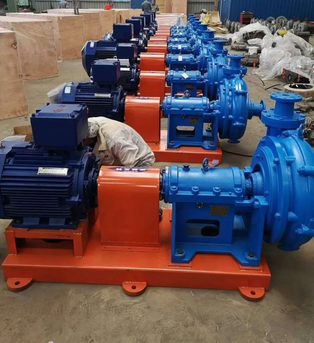
A slurry pump impeller is the primary kinetic energy transfer component within a centrifugal pump designed to transport abrasive fluids, tailings, and chemical slurries. Positioned as the critical interface between the mechanical drive and the fluid medium, the impeller's primary function is to convert rotational energy into hydrodynamic pressure. In the industrial supply chain, wholesale slurry pump impellers are categorized by their metallurgy and vane geometry, serving sectors such as mineral processing, dredging, and wastewater treatment. The technical efficacy of an impeller is measured by its ability to maintain hydraulic efficiency while resisting the extreme erosive and corrosive forces inherent in multi-phase flow environments. Achieving a balance between volumetric flow rate and the longevity of the wear surfaces is the central engineering challenge in slurry pump design.
Material Science & Manufacturing
The operational environment of a slurry pump impeller involves simultaneous abrasion (mechanical wear) and corrosion (chemical degradation), a phenomenon known as corrosion-erosion. To combat this, material selection is governed by the hardness and chemical stability of the alloy. High-Chrome White Irons (ASTM A532) are the industry standard, typically containing 25% to 28% chromium. The microstructure consists of hard M7C3 carbides embedded in a martensitic matrix, providing a hardness range of 58-65 HRC. For highly acidic or alkaline slurries, duplex stainless steels or rubber-lined composite structures are employed to prioritize chemical inertia over raw hardness.
Manufacturing begins with precision investment casting or sand casting, followed by a rigorous heat treatment process. Austenitizing and quenching are critical to ensure the transformation of austenite into martensite, preventing internal stresses that could lead to premature fracturing under hydraulic shock. Once cast, the impeller undergoes dynamic balancing to ISO 1940-1 standards to eliminate centrifugal vibration. The final stage involves CNC machining of the bore and keyway, followed by precision grinding of the vane profiles. Key parameter control focuses on the "throat area" and "vane thickness," as deviations of even 0.5mm can lead to turbulent flow, increasing the localized velocity and accelerating erosive wear.
Performance & Engineering
The engineering of a slurry pump impeller revolves around the Fluid Dynamics (CFD) of non-Newtonian fluids. Force analysis reveals that the highest wear occurs at the vane leading edges and the impeller eye, where the fluid velocity is highest. To mitigate this, engineers utilize "open" or "semi-open" impeller designs to reduce clogging and minimize the friction loss associated with high-solid-content slurries. The specific speed (Ns) is calculated to optimize the impeller diameter and width for the required head and flow rate.
Environmental resistance is managed through the implementation of specialized coatings and the optimization of the Reynolds number to maintain a stable boundary layer. Compliance requirements demand that the impeller withstand the "slugging" effect—sudden increases in solids concentration that create massive torque spikes. Engineering calculations must account for the slurry's specific gravity (often ranging from 1.1 to 1.8), which significantly increases the radial load on the shaft and the centrifugal force acting on the impeller vanes. The integration of a wear plate and the maintenance of a precise clearance between the impeller and the suction liner are vital to prevent internal recirculation, which would otherwise lead to rapid cavitation erosion.
Technical Specifications
| Material Grade | Hardness (HRC) | Corrosion Resistance | Max Particle Size (mm) |
|---|---|---|---|
| High Chrome Alloy (A05) | 60 - 65 | Moderate | 12 - 25 |
| Duplex Stainless Steel | 25 - 35 | Excellent | 5 - 15 |
| Hardened Cast Iron | 45 - 52 | Low | 8 - 20 |
| Rubber Lined Composite | N/A (Elastic) | High | 2 - 10 |
| Tungsten Carbide Coated | 70+ | High | 10 - 20 |
| Nickel-Chrome Alloy | 50 - 58 | Very High | 10 - 15 |
Failure Mode & Maintenance
Failure analysis of slurry pump impellers typically reveals four primary modes: Erosive Wear, Cavitation, Fatigue Cracking, and Chemical Pitting. Erosive wear is characterized by the gradual thinning of the vane trailing edges, caused by the constant impact of abrasive particles. Cavitation occurs when the Net Positive Suction Head (NPSH) is insufficient, creating vapor bubbles that implode against the impeller surface, leaving a "pitted" or "sponge-like" appearance. Fatigue cracking often originates at the keyway or the hub due to cyclic loading and vibration, eventually leading to catastrophic structural failure.
Professional maintenance requires a predictive approach. Regular vibration analysis using accelerometers can detect imbalance caused by uneven wear before it damages the bearings. Maintenance protocols should include the use of ultrasonic thickness gauges to measure vane degradation without dismantling the pump. When wear exceeds 15% of the original thickness, the impeller should be replaced or hard-faced using Laser Cladding or HVOF (High-Velocity Oxy-Fuel) spraying. To prevent premature failure, operators must ensure that the pump is operated as close to the Best Efficiency Point (BEP) as possible to minimize internal turbulence.
Industry FAQ
Q: How do we determine if a High Chrome impeller is more suitable than a Rubber-lined one?
A: The decision is based on particle size and chemical composition. High Chrome is superior for large, hard particles (e.g., quartz or iron ore) where abrasive wear dominates. Rubber-lined impellers are preferred for fine particles and highly corrosive chemicals where the elastic property of rubber allows it to absorb the impact of particles without material loss.
Q: What causes the sudden "pitting" observed on the impeller vanes?
A: This is typically a result of cavitation. It occurs when the fluid pressure drops below the vapor pressure, forming bubbles that collapse violently. This is often caused by a restricted suction line, a clogged strainer, or operating the pump too far to the right of the performance curve.
Q: Can we increase the impeller diameter to achieve a higher head?
A: While increasing the diameter increases the head, it also increases the radial load on the shaft and the required motor torque. This can lead to shaft deflection and accelerated wear on the seals and bearings. A comprehensive power analysis must be performed before modifying the diameter.
Q: How does the "specific speed" influence the impeller geometry?
A: Low specific speed impellers are narrow and have a large diameter to create high pressure (head), whereas high specific speed impellers are wider and shorter to move larger volumes of fluid. For slurry pumps, the geometry is further modified to ensure that solids do not settle in the impeller eye.
Q: What is the impact of "air entrainment" on impeller lifespan?
A: Air entrainment disrupts the hydraulic flow and can cause "air binding," leading to erratic pressure fluctuations. These fluctuations increase the risk of fatigue cracking and accelerate cavitation, significantly reducing the Mean Time Between Failures (MTBF).
Conclusion
The technical integrity of a slurry pump impeller depends on the precise synchronization of material hardness, hydraulic geometry, and manufacturing precision. By utilizing High-Chrome alloys and optimizing vane profiles through CFD analysis, industry operators can significantly reduce the degradation rates caused by corrosive-erosive synergy. The selection of the impeller must be a data-driven process, considering the slurry's specific gravity, particle size distribution, and the chemical pH of the medium.
Looking forward, the integration of smart monitoring sensors and advanced additive manufacturing (3D metal printing) promises to further optimize impeller efficiency and lead times. For procurement managers and engineers, the priority remains the transition from reactive replacement to predictive maintenance, ensuring that the slurry pump remains a reliable link in the industrial production chain.
-
basement bathroom sewage pump Material Science Manufacturing
News2026-05-21
-
wastewater treatment plant pumps Material Science Manufacturing
News2026-05-21
-
waste water pump for basement Material Science Manufacturing
News2026-05-21
-
sump pump sewage Performance Analysis
News2026-05-21
-
sump pump for sewage Material Science and Manufacturing
News2026-05-21
-
sump pump for septic systems Material Science Manufacturing
News2026-05-20
-
sump pump and ejector pump Material Science Manufacturing
News2026-05-20
-
sewage treatment plant pumps Performance Analysis
News2026-05-20
-
sewage tank pump Material Science and Manufacturing
News2026-05-20
-
sewage pump for septic tank Performance Analysis
News2026-05-20
-
Sewage Pump and Tank Performance Analysis
News2026-05-19
-
Sewage Ejector Pump Replacement Performance Analysis
News2026-05-19
-
sewage ejector pump for basement bathroom Material Science Manufacturing
News2026-05-19
-
sewage ejection pump Material Science and Manufacturing
News2026-05-19
-
in line sewage pump Performance Analysis
News2026-05-19


