English
- Afrikaans
- Albanian
- Amharic
- Arabic
- Armenian
- Azerbaijani
- Basque
- Belarusian
- Bengali
- Bosnian
- Bulgarian
- Catalan
- Cebuano
- Corsican
- Croatian
- Czech
- Danish
- Dutch
- English
- Esperanto
- Estonian
- Finnish
- French
- Frisian
- Galician
- Georgian
- German
- Greek
- Gujarati
- Haitian Creole
- hausa
- hawaiian
- Hebrew
- Hindi
- Miao
- Hungarian
- Icelandic
- igbo
- Indonesian
- irish
- Italian
- Japanese
- Javanese
- Kannada
- kazakh
- Khmer
- Rwandese
- Korean
- Kurdish
- Kyrgyz
- Lao
- Latin
- Latvian
- Lithuanian
- Luxembourgish
- Macedonian
- Malgashi
- Malay
- Malayalam
- Maltese
- Maori
- Marathi
- Mongolian
- Myanmar
- Nepali
- Norwegian
- Norwegian
- Occitan
- Pashto
- Persian
- Polish
- Portuguese
- Punjabi
- Romanian
- Russian
- Samoan
- Scottish Gaelic
- Serbian
- Sesotho
- Shona
- Sindhi
- Sinhala
- Slovak
- Slovenian
- Somali
- Spanish
- Sundanese
- Swahili
- Swedish
- Tagalog
- Tajik
- Tamil
- Tatar
- Telugu
- Thai
- Turkish
- Turkmen
- Ukrainian
- Urdu
- Uighur
- Uzbek
- Vietnamese
- Welsh
- Bantu
- Yiddish
- Yoruba
- Zulu
 Co., Ltd.")
Telephone: +86 13120555503
Email: frank@cypump.com


Apr . 01, 2024 17:55 Back to list
wholesale medium head heavy duty slurry pump Performance Analysis
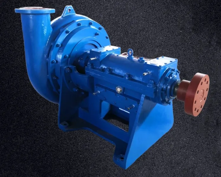
Medium Head Heavy Duty Slurry Pump Performance Analysis
The medium head heavy duty slurry pump is a specialized centrifugal machine engineered for the transport of high-density, abrasive fluids containing suspended solid particles. Occupying a critical position in the industrial chain—specifically within mineral processing, dredging, and chemical waste management—these pumps are designed to bridge the gap between low-head high-volume transfer and high-head low-volume pressure systems. The core technical challenge of a medium head slurry pump lies in balancing the hydraulic efficiency of the impeller with the extreme wear resistance required to handle slurry. To achieve this, the pump must maintain a stable Total Dynamic Head (TDH) while resisting the erosive forces of particulate matter, ensuring that the volumetric efficiency remains consistent despite the non-Newtonian behavior of the transported medium.
Material Science & Manufacturing
The longevity of a heavy duty slurry pump is fundamentally determined by its metallurgical composition and the precision of its manufacturing process. Given the constant abrasion and potential corrosion from chemical agents in the slurry, material selection focuses on high-chromium alloys and specialized elastomers.
Metallurgical Structure: For the impeller and liner, high-chromium white iron (e.g., ASTM A532) is typically employed. These materials feature a hard martensitic matrix with embedded primary M7C3 carbides. These carbides provide the requisite hardness (typically 60-65 HRC) to resist micro-plowing and cutting by abrasive particles. For applications involving acidic or alkaline slurries, duplex stainless steels are utilized to prevent pitting and stress corrosion cracking.
Manufacturing Process: The fabrication starts with precision casting, where centrifugal casting is often used for the liner to ensure a dense, pore-free structure. The impeller undergoes dynamic balancing to ISO 1940-1 standards to minimize vibration and prevent premature bearing failure. CNC machining is applied to the wearing plates and shaft interfaces to ensure a tolerance fit within microns, reducing the gap between the impeller and the wear plate, which significantly minimizes recirculation and energy loss. Finally, the pump casing is pressure tested to 1.5 times the maximum working pressure to ensure structural integrity under hydraulic surge conditions.
Performance & Engineering
Engineering a medium head heavy duty slurry pump requires a deep analysis of fluid dynamics and mechanical stress. The primary goal is to maximize the "Mean Time Between Failure" (MTBF) while maintaining the required flow rate and head.
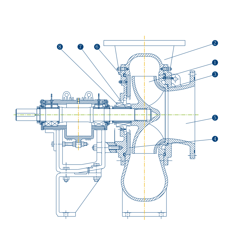
Hydraulic Design & Force Analysis: The impeller is designed with a semi-open or closed geometry to optimize the conversion of kinetic energy into pressure. Engineers must account for the "slurry effect," where the increased density of the fluid increases the radial load on the shaft. To counteract this, heavy-duty double-row angular contact bearings or spherical roller bearings are used to accommodate slight shaft deflections without compromising rotational stability.
Environmental Resistance & Compliance: The pump must operate in extreme environments, often exposed to fluctuating temperatures and corrosive atmospheres. The sealing system is a critical engineering component; typically, a combination of an expeller seal (to keep solids away from the stuffing box) and a gland seal with a pressurized flushing system is used. This prevents the abrasive slurry from entering the bearing housing. Engineering compliance focuses on the NPSHr (Net Positive Suction Head required) to prevent cavitation, which can lead to catastrophic material loss in the impeller eye.
Technical Specifications
| Parameter Category | Standard Specification | High-Performance Range | Operational Tolerance |
|---|---|---|---|
| Maximum Flow Rate | 200 - 1,500 m³/h | Up to 2,500 m³/h | ± 5% of Nominal Flow |
| Total Dynamic Head (TDH) | 20 - 60 meters | Up to 80 meters | ± 2% Hydraulic Variance |
| Material Hardness | 55 - 62 HRC | 65 - 70 HRC (Special Alloy) | ± 2 HRC across surface |
| Max Particle Size | 10mm - 50mm | Up to 100mm | Dependent on Impeller Eye |
| Slurry Density | 1.1 - 1.4 t/m³ | Up to 1.8 t/m³ | ± 0.05 t/m³ |
| Seal Type | Mechanical/Expeller | Double Mechanical Seal | Leakage < 5 drops/min |
Failure Mode & Maintenance
Understanding the failure modes of slurry pumps is essential for reducing operational downtime. The most common failures are categorized as follows:
1. Abrasive Wear & Erosion: This is the primary failure mode. It manifests as the thinning of the impeller vanes and the enlargement of the volute casing. This occurs due to the high-velocity impact of solids. Solution: Implement a scheduled rotation of the impeller and the replacement of replaceable liner plates. Use a Hard-Facing weld overlay if wear is localized.
2. Cavitation Pitting: Occurs when the NPSH available is lower than the NPSH required, causing vapor bubbles to collapse violently against the metal surface. This creates a "sponge-like" appearance on the impeller. Solution: Increase the suction head or reduce the fluid temperature to lower the vapor pressure.
3. Shaft Fatigue & Deflection: Excessive radial loads from high-density slurry can lead to shaft bending or fatigue cracking near the bearing seat. Solution: Regular vibration analysis using accelerometers to detect imbalances and ensuring the pump is perfectly aligned with the motor using laser alignment tools.
4. Seal Degradation: The ingress of abrasive particles into the seal faces causes rapid scoring and leakage. Solution: Maintain the seal flush water pressure at 1 bar higher than the pump discharge pressure to ensure a positive outward flow of clean water.
Industry FAQ
Q: How do we determine the correct impeller material for a medium head slurry pump based on the slurry composition?
A: The selection depends on the Mohs hardness of the particles and the pH of the liquid. For silica-based slurries (Hardness 7), High-Chrome alloys (27% Cr) are mandatory. If the slurry contains sulfuric acid, we specify duplex stainless steel or rubber-lined components to prevent chemical corrosion while maintaining structural integrity.
Q: What is the impact of increasing the slurry concentration on the pump's Total Dynamic Head?
A: Increasing concentration increases the fluid's viscosity and density, which elevates the friction loss in the piping. This effectively increases the system head, potentially shifting the pump's operating point to the left on the performance curve, resulting in lower flow rates and higher power consumption.
Q: Can the medium head pump handle air entrainment in the slurry?
A: Excessive air entrainment can lead to "air binding" or erratic flow, which causes pressure surges and cavitation. We recommend installing an air release valve at the highest point of the suction line or utilizing a specialized vortex breaker in the sump to minimize air intake.
Q: How often should the wear liners be inspected in a heavy-duty mining application?
A: In high-abrasion environments, we recommend an ultrasonic thickness measurement every 500 to 1,000 operational hours. Once the liner thickness reaches 20% of its original dimension, it must be replaced to prevent the slurry from eroding the outer structural casing.
Q: Why is a variable frequency drive (VFD) recommended for medium head slurry pumps?
A: A VFD allows the operator to adjust the pump speed to match the actual slurry density and flow requirements. This prevents the pump from operating too far from its Best Efficiency Point (BEP), which significantly reduces vibration and extends the life of the bearings and seals.
Conclusion
The operational efficiency of a medium head heavy duty slurry pump is the result of a rigorous synergy between advanced material science and precise hydraulic engineering. By utilizing high-chromium alloys and optimizing the internal flow paths, these pumps are capable of managing the extreme stresses of abrasive transport. The technical focus must remain on the management of wear rates and the maintenance of hydraulic balance to ensure long-term viability in industrial applications.
Moving forward, the integration of IoT-based vibration monitoring and smart sealing systems will likely redefine maintenance protocols, shifting from scheduled replacements to predictive maintenance. For procurement and engineering teams, the priority should be a holistic evaluation of the slurry's chemical and physical properties to select the optimal metallurgical configuration, thereby maximizing the lifecycle value and operational uptime of the pumping system.
-
basement bathroom sewage pump Material Science Manufacturing
News2026-05-21
-
wastewater treatment plant pumps Material Science Manufacturing
News2026-05-21
-
waste water pump for basement Material Science Manufacturing
News2026-05-21
-
sump pump sewage Performance Analysis
News2026-05-21
-
sump pump for sewage Material Science and Manufacturing
News2026-05-21
-
sump pump for septic systems Material Science Manufacturing
News2026-05-20
-
sump pump and ejector pump Material Science Manufacturing
News2026-05-20
-
sewage treatment plant pumps Performance Analysis
News2026-05-20
-
sewage tank pump Material Science and Manufacturing
News2026-05-20
-
sewage pump for septic tank Performance Analysis
News2026-05-20
-
Sewage Pump and Tank Performance Analysis
News2026-05-19
-
Sewage Ejector Pump Replacement Performance Analysis
News2026-05-19
-
sewage ejector pump for basement bathroom Material Science Manufacturing
News2026-05-19
-
sewage ejection pump Material Science and Manufacturing
News2026-05-19
-
in line sewage pump Performance Analysis
News2026-05-19


