English
- Afrikaans
- Albanian
- Amharic
- Arabic
- Armenian
- Azerbaijani
- Basque
- Belarusian
- Bengali
- Bosnian
- Bulgarian
- Catalan
- Cebuano
- Corsican
- Croatian
- Czech
- Danish
- Dutch
- English
- Esperanto
- Estonian
- Finnish
- French
- Frisian
- Galician
- Georgian
- German
- Greek
- Gujarati
- Haitian Creole
- hausa
- hawaiian
- Hebrew
- Hindi
- Miao
- Hungarian
- Icelandic
- igbo
- Indonesian
- irish
- Italian
- Japanese
- Javanese
- Kannada
- kazakh
- Khmer
- Rwandese
- Korean
- Kurdish
- Kyrgyz
- Lao
- Latin
- Latvian
- Lithuanian
- Luxembourgish
- Macedonian
- Malgashi
- Malay
- Malayalam
- Maltese
- Maori
- Marathi
- Mongolian
- Myanmar
- Nepali
- Norwegian
- Norwegian
- Occitan
- Pashto
- Persian
- Polish
- Portuguese
- Punjabi
- Romanian
- Russian
- Samoan
- Scottish Gaelic
- Serbian
- Sesotho
- Shona
- Sindhi
- Sinhala
- Slovak
- Slovenian
- Somali
- Spanish
- Sundanese
- Swahili
- Swedish
- Tagalog
- Tajik
- Tamil
- Tatar
- Telugu
- Thai
- Turkish
- Turkmen
- Ukrainian
- Urdu
- Uighur
- Uzbek
- Vietnamese
- Welsh
- Bantu
- Yiddish
- Yoruba
- Zulu
 Co., Ltd.")
Telephone: +86 13120555503
Email: frank@cypump.com


Apr . 01, 2024 17:55 Back to list
Slurry Pumps for Sale Performance Analysis and Manufacturing Specifications
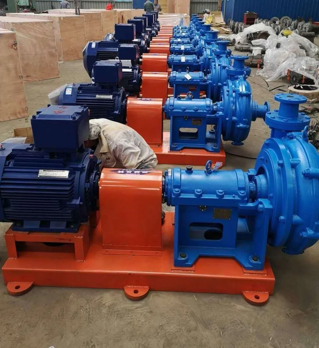
Slurry Pumps: Performance Analysis and Manufacturing Specifications
Slurry pumps are highly specialized centrifugal pumps designed to transport fluids containing suspended solid particles, ranging from fine silts to coarse minerals and abrasive ores. Positioned as critical infrastructure in the mining, dredging, and chemical processing industry chains, these machines must navigate the paradox of maintaining high hydraulic efficiency while resisting extreme mechanical wear. The core technical challenge lies in the management of non-Newtonian fluid dynamics and the mitigation of abrasive erosion. A high-performance slurry pump is defined by its ability to handle high specific gravity fluids, maintain a stable Net Positive Suction Head (NPSH), and extend the Mean Time Between Failure (MTBF) through advanced metallurgy and precision engineering of the impeller and volute geometry.
Material Science & Manufacturing
The longevity of a slurry pump is fundamentally determined by the material science employed in its wetted parts. Because the fluid medium is inherently abrasive, standard stainless steels are insufficient. The industry utilizes high-chromium white irons (e.g., ASTM A532), which combine a hard chromium carbide network with a martensitic matrix, providing a hardness typically exceeding 60 HRC. For extreme abrasion-corrosion environments, duplex stainless steels or specialized rubber linings (such as natural rubber or nitrile) are deployed to absorb the kinetic energy of impacting particles, thereby reducing surface material loss.
Manufacturing processes focus on the structural integrity of the casing and the balance of the rotating assembly. Investment casting is utilized for impellers to ensure complex hydraulic profiles, followed by rigorous heat treatment—specifically quenching and tempering—to eliminate internal stresses and optimize hardness gradients. The manufacturing of the shaft involves precision forging and grinding to ensure concentricity within microns, reducing vibration that could otherwise accelerate seal failure. Key parameter control during production includes the strict monitoring of the carbon-equivalent value in alloys to prevent cold cracking and the use of CNC machining to ensure that the tolerances between the impeller and the wear plate are minimized to prevent recirculation and internal erosion.
Performance & Engineering
Engineering a slurry pump requires a deep analysis of fluid-solid interactions. The primary objective is to minimize the relative velocity between the slurry and the pump walls, as erosion rates typically increase exponentially with velocity. Hydraulic design focuses on optimizing the impeller vane angle and the volute's spiral geometry to maintain a laminar flow profile wherever possible, reducing the turbulence that leads to localized "hot spots" of wear.
Force analysis is critical, particularly concerning radial thrust. As the pump operates away from its Best Efficiency Point (BEP), unbalanced radial forces can lead to shaft deflection and premature bearing failure. To counter this, engineers implement reinforced bearing housings and heavy-duty shafts with optimized diameters. Environmental resistance is addressed through the implementation of advanced sealing systems; expelled seals (which use a flushed water jacket to push solids away from the shaft) are the industry standard for preventing particulate ingress into the bearing chamber. Compliance requirements dictate that these pumps meet stringent vibration and noise limits, ensuring stability during 24/7 continuous operation in harsh industrial settings.
Technical Specifications
| Technical Parameter | High-Chrome Alloy Model | Rubber-Lined Model | Duplex Steel Model | Evaluation Metric |
|---|---|---|---|---|
| Max Flow Rate (m³/h) | 1200 | 800 | 1000 | Volumetric Efficiency |
| Max Discharge Head (m) | 65 | 45 | 60 | Hydraulic Gradient |
| Hardness (HRC) | 62-68 | N/A (Elastic) | 25-35 | Abrasion Resistance |
| Max Solid Particle Size (mm) | 110 | 70 | 90 | Passage Clearance |
| Max Slurry Density (kg/m³) | 1.5 - 1.8 | 1.2 - 1.5 | 1.4 - 1.7 | Specific Gravity |
| Operating Temperature (°C) | -20 to 150 | -10 to 70 | -40 to 200 | Thermal Stability |
Failure Mode & Maintenance
Failure analysis in slurry pumps reveals four primary degradation modes: abrasive wear, corrosive pitting, fatigue cracking, and cavitation. Abrasive wear typically manifests as "grooving" in the volute or thinning of the impeller vanes, caused by the high-velocity impingement of hard particles. Corrosive pitting occurs when the passive layer of the metal is mechanically stripped by the slurry, exposing raw metal to acidic or alkaline fluids. Fatigue cracking is often a result of cyclic loading caused by vibration or operation at low flow rates, leading to structural failure of the shaft. Cavitation occurs when the NPSH available is lower than the NPSH required, creating vapor bubbles that implode and cause micro-pitting on the impeller surface.
Professional maintenance requires a predictive strategy. Vibration analysis (using accelerometers) is employed to detect bearing wear before catastrophic failure occurs. Wear liners should be monitored using ultrasonic thickness gauges to determine the precise moment of replacement. For seal maintenance, the flush water pressure must be kept 1-2 bar higher than the pump internal pressure to ensure the positive displacement of solids. When replacing impellers, dynamic balancing to ISO 1940 standards is mandatory to prevent the introduction of new harmonic vibrations into the system.
Industry FAQ
Q: How do I determine whether a high-chrome alloy or a rubber-lined pump is more suitable for my application?
A: The choice depends on the particle size and the nature of the abrasion. High-chrome alloys are superior for coarse, large particles with high hardness that would tear through rubber. Rubber lining is more effective for fine, sharp particles that "sandblast" the surface, as the elastomer absorbs the impact energy.
Q: What is the impact of slurry viscosity on the NPSH requirements of the pump?
A: Increased viscosity increases the frictional losses in the suction piping, which reduces the NPSH available. This elevates the risk of cavitation. To mitigate this, we recommend increasing the suction pipe diameter or lowering the pump installation height relative to the slurry source.
Q: Why is my pump experiencing premature failure of the mechanical seals despite regular flushing?
A: This is often caused by "settling" during downtime. If the pump is stopped without being flushed, solids settle at the seal face. Upon restart, these particles act as abrasives, scoring the seal faces. Implementing an automated pre-start flush cycle can resolve this.
Q: Can these pumps handle non-Newtonian fluids, such as Bingham plastics?
A: Yes, but the hydraulic curves must be derated. Non-Newtonian fluids exhibit a yield stress that requires higher starting torque and alters the flow profile. We adjust the motor sizing and impeller geometry to ensure the fluid is sufficiently sheared to maintain flow.
Q: How does the "critical speed" of the shaft affect the selection of the drive motor?
A: The shaft's critical speed must be at least 20% higher than the maximum operating speed to avoid resonance. The motor must be coupled via a flexible coupling that can dampen these frequencies and accommodate the high starting torque required to move a static column of heavy slurry.
Conclusion
The selection and operation of slurry pumps are governed by the complex interplay between metallurgical hardness and hydraulic efficiency. To ensure operational stability, it is imperative to align the material properties of the pump—whether high-chrome alloy or rubber-lined—with the specific abrasive and corrosive characteristics of the medium. By focusing on the reduction of relative velocity and the implementation of rigorous seal-flushing protocols, operators can significantly extend the component lifecycle and reduce total cost of ownership.
Looking forward, the integration of IoT-based condition monitoring, such as real-time wear sensors and acoustic emission analysis, will transition slurry pump maintenance from a reactive to a prescriptive model. Engineering teams should prioritize the adoption of these technologies and adhere to international standards to optimize throughput and minimize unscheduled downtime in high-demand industrial environments.
-
sump pump for septic systems Material Science Manufacturing
News2026-05-20
-
sump pump and ejector pump Material Science Manufacturing
News2026-05-20
-
sewage treatment plant pumps Performance Analysis
News2026-05-20
-
sewage tank pump Material Science and Manufacturing
News2026-05-20
-
sewage pump for septic tank Performance Analysis
News2026-05-20
-
Sewage Pump and Tank Performance Analysis
News2026-05-19
-
Sewage Ejector Pump Replacement Performance Analysis
News2026-05-19
-
sewage ejector pump for basement bathroom Material Science Manufacturing
News2026-05-19
-
sewage ejection pump Material Science and Manufacturing
News2026-05-19
-
in line sewage pump Performance Analysis
News2026-05-19
-
effluent sump pump Performance Analysis
News2026-05-18
-
best grinder pump for sewage Performance Engineering
News2026-05-18
-
basement waste water pump Performance Engineering
News2026-05-18
-
sump pump sewer Performance Analysis
News2026-05-18
-
sump pump for sewer Performance Analysis
News2026-05-18


