English
- Afrikaans
- Albanian
- Amharic
- Arabic
- Armenian
- Azerbaijani
- Basque
- Belarusian
- Bengali
- Bosnian
- Bulgarian
- Catalan
- Cebuano
- Corsican
- Croatian
- Czech
- Danish
- Dutch
- English
- Esperanto
- Estonian
- Finnish
- French
- Frisian
- Galician
- Georgian
- German
- Greek
- Gujarati
- Haitian Creole
- hausa
- hawaiian
- Hebrew
- Hindi
- Miao
- Hungarian
- Icelandic
- igbo
- Indonesian
- irish
- Italian
- Japanese
- Javanese
- Kannada
- kazakh
- Khmer
- Rwandese
- Korean
- Kurdish
- Kyrgyz
- Lao
- Latin
- Latvian
- Lithuanian
- Luxembourgish
- Macedonian
- Malgashi
- Malay
- Malayalam
- Maltese
- Maori
- Marathi
- Mongolian
- Myanmar
- Nepali
- Norwegian
- Norwegian
- Occitan
- Pashto
- Persian
- Polish
- Portuguese
- Punjabi
- Romanian
- Russian
- Samoan
- Scottish Gaelic
- Serbian
- Sesotho
- Shona
- Sindhi
- Sinhala
- Slovak
- Slovenian
- Somali
- Spanish
- Sundanese
- Swahili
- Swedish
- Tagalog
- Tajik
- Tamil
- Tatar
- Telugu
- Thai
- Turkish
- Turkmen
- Ukrainian
- Urdu
- Uighur
- Uzbek
- Vietnamese
- Welsh
- Bantu
- Yiddish
- Yoruba
- Zulu
 Co., Ltd.")
Telephone: +86 13120555503
Email: frank@cypump.com


Apr . 01, 2024 17:55 Back to list
slurry pump impeller Manufacturing Specification and Performance Analysis
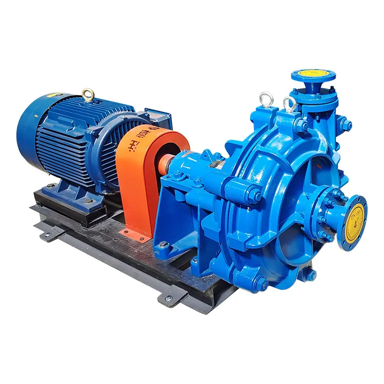
Slurry Pump Impeller Manufacturing Specification and Performance Analysis
The slurry pump impeller serves as the primary kinetic energy transfer component within heavy-duty centrifugal pumps designed for the transport of abrasive solids suspended in liquid. Positioned at the core of the hydraulic circuit, the impeller is subjected to extreme conditions, including high-velocity impingement of particulate matter, corrosive chemical environments, and significant hydraulic turbulence. Technically, the impeller must balance the contradictory requirements of high hydraulic efficiency and extreme wear resistance. Its primary function is to convert mechanical energy from the motor into kinetic energy and pressure head, ensuring the continuous transport of mine tailings, mineral slurries, and chemical waste without premature structural failure. In the industrial chain, the impeller is the highest-wear component, meaning its material composition and geometric precision directly dictate the Mean Time Between Failure (MTBF) and the overall operational expenditure (OPEX) of the pumping system.
Material Science & Manufacturing
The selection of materials for slurry pump impellers is governed by the synergy between hardness and toughness. The industry predominantly utilizes High-Chromium (Hi-Cr) White Cast Irons and specialized Elastomers, depending on the slurry's particle size and chemical aggressiveness.
1. High-Chromium White Cast Iron (ASTM A532): For highly abrasive slurries, alloys containing 12% to 28% Chromium are employed. The metallurgy focuses on the formation of primary M7C3 carbides—hard chromium carbides embedded in a martensitic matrix. This microstructure provides a hardness typically exceeding 60 HRC, which is essential to resist the micro-cutting and plowing actions of silica or iron ore particles. The cooling rate during casting is strictly controlled to prevent the formation of coarse eutectic carbides, which would otherwise introduce brittleness and susceptibility to impact cracking.
2. Polyurethane and Natural Rubber: In applications involving finer particles at higher velocities, elastomeric impellers are preferred. These materials operate on the principle of "resilience," where the material absorbs the energy of the impacting particle and rebounds, rather than resisting it through hardness. The chemical bonding process involves vulcanization to ensure the rubber maintains its structural integrity under high centrifugal forces.
3. Manufacturing Process Flow:
- Precision Casting: The process begins with investment casting or sand casting using high-density molds to ensure dimensional accuracy of the vane profiles.
- Heat Treatment: For Hi-Cr alloys, a rigorous quenching and tempering cycle is applied. This transforms the austenite into tempered martensite, optimizing the balance between wear resistance and fracture toughness.
- Dynamic Balancing: To prevent vibration and bearing failure, impellers undergo ISO 1940-1 G2.5 or G6.3 grade dynamic balancing. This involves removing minute amounts of material from non-critical areas to ensure the center of mass coincides with the axis of rotation.
- Surface Finishing: Critical sealing surfaces and the hub bore are precision-ground to ensure a tight interference fit with the shaft, minimizing leakage and parasitic losses.
Performance & Engineering
Engineering a slurry pump impeller requires a deep analysis of fluid dynamics (CFD) and structural mechanics to mitigate the effects of erosion-corrosion. The core engineering challenge is the management of the "velocity gradient" near the vane surfaces.
1. Hydraulic Force Analysis: The impeller must generate sufficient head (H) to overcome system friction while maintaining a flow rate (Q) that prevents the solids from settling (critical velocity). The vane angle is optimized to reduce turbulence and prevent "recirculation zones" where particles can concentrate and cause localized accelerated wear.
2. Erosion-Corrosion Interaction: In many mining applications, the slurry is not only abrasive but also acidic or alkaline. This creates a synergistic effect: the abrasive particles strip away the protective oxide layer (passive film) from the metal surface, exposing fresh metal to chemical corrosion, which in turn weakens the material's bond, making it easier for particles to remove further material. To counter this, molybdenum and nickel are often added to the alloy to enhance the repassivation rate of the surface.
3. Centrifugal Stress and Deformation: Under high RPM, the impeller experiences significant centrifugal stress. The thickness of the impeller shroud and the reinforcement of the hub are calculated to ensure that the Von Mises stress remains well below the yield strength of the material, preventing plastic deformation that would lead to impeller-casing contact.
Technical Specifications
| Material Grade | Hardness (HRC/Shore A) | Abrasion Resistance Index | Max. Operating Temp | Corrosion Resistance | Application Type |
|---|---|---|---|---|---|
| High-Cr White Iron (27% Cr) | 62 - 66 HRC | Ultra-High | 450°C | Moderate | Coarse Tailings/Mining |
| Chrome-Moly Steel | 45 - 52 HRC | Medium-High | 500°C | High | Acidic Slurries |
| Natural Rubber (NR) | 60 - 80 Shore A | High (Fine Particles) | 70°C | Excellent | Fine Sand/Water |
| Polyurethane (PU) | 90 - 95 Shore A | Very High | 90°C | High | Oil-based Slurries |
| Duplex Stainless Steel | 30 - 40 HRC | Medium | 300°C | Ultra-High | Seawater/Chemical |
| Ceramic Composite | >70 HRC | Extreme | 800°C | Extreme | Highly Aggressive Acids |
Failure Mode & Maintenance
Failure analysis of slurry pump impellers typically reveals four primary modes of degradation, each requiring a specific mitigation strategy.
1. Abrasive Wear (Erosion): This is the most common failure mode, characterized by the thinning of vane leading edges and the enlargement of the impeller eye. It occurs due to the kinetic energy of particles impacting the surface. Maintenance: Implement a scheduled measurement of vane thickness using ultrasonic gauges. Replace impellers when the efficiency drops by 10% or wear exceeds 25% of the original thickness.
2. Cavitation Pitting: Occurs when the Net Positive Suction Head Available (NPSHa) is lower than the NPSH Required (NPSHr). Vapor bubbles collapse violently against the impeller surface, creating micro-jets that pit the material. Maintenance: Increase suction head or reduce pump speed. Inspect for "sponge-like" surface textures on the suction side of the vanes.
3. Fatigue Cracking: Induced by cyclic loading, especially in pumps handling non-homogeneous slurries with large boulders. This leads to cracks originating from the hub or vane roots. Maintenance: Perform Non-Destructive Testing (NDT) such as Dye Penetrant Inspection (DPI) during annual overhauls to detect sub-surface cracks.
4. Chemical Degradation: For rubber impellers, this manifests as swelling, hardening, or "chunking" due to incompatibility with the fluid (e.g., exposure to hydrocarbons). Maintenance: Verify the chemical compatibility matrix before material selection and monitor the Shore hardness of the rubber over time.
Industry FAQ
Q: How do I determine whether to use a High-Chrome or a Rubber impeller for a specific application?
A: The decision is based primarily on particle size and velocity. High-Chrome alloys are superior for coarse, large-diameter particles that cause high-impact stress. Rubber is more effective for fine particles at high velocities, as the material's elasticity allows it to absorb the impact energy rather than being eroded.
Q: Why does my impeller show accelerated wear at the vane tips specifically?
A: This is typically due to high relative velocity and turbulence at the periphery. If the clearance between the impeller tip and the wear plate is too large, "internal recirculation" occurs, causing particles to loop back and strike the tips repeatedly, accelerating wear.
Q: Can the use of a Variable Frequency Drive (VFD) extend the impeller's lifespan?
A: Yes. Wear rates in slurry pumps are generally proportional to the cube of the velocity (V³). By using a VFD to operate the pump at the minimum required speed to maintain transport velocity, you can exponentially reduce the erosion rate.
Q: What is the significance of "Dynamic Balancing" for a heavy slurry impeller?
A: Because slurry impellers are often cast from heavy alloys with potential internal porosity, they can have inherent imbalances. Even a small offset in the center of mass at high RPM generates massive centrifugal forces that can destroy pump bearings and seals within hours.
Q: How can I identify the difference between cavitation and erosion during a teardown?
A: Erosion usually appears as smooth, directional "grooves" or thinning in the direction of flow. Cavitation appears as localized, jagged, "pock-marked" craters, often occurring on the suction side or near the vane leading edges, independent of the flow direction.
Conclusion
The slurry pump impeller is a critical engineering component where material science and hydraulic design intersect. The transition from standard alloys to high-chromium white irons and specialized elastomers has allowed the industry to handle increasingly aggressive media. However, the longevity of the impeller is not solely dependent on the material, but on the precise control of manufacturing parameters—specifically heat treatment, dynamic balancing, and the optimization of the hydraulic profile to minimize turbulence.
Looking forward, the integration of Computational Fluid Dynamics (CFD) and 3D printing (Additive Manufacturing) for rapid prototyping of impeller geometries will allow for further efficiency gains and targeted wear-resistant coatings. For procurement and engineering teams, the focus must remain on a holistic approach: matching the material's metallurgical properties to the specific particle morphology and chemical nature of the slurry to ensure maximum operational uptime.
-
Comprehensive Guide to Waterproof ORings for Optimal Sealing Solutions
News2026-06-09
-
Waste Tank Pump Performance Analysis
News2026-06-27
-
Sewer System Pump Out Material Science
News2026-06-27
-
Sewer Ejector Pit Performance Analysis
News2026-06-27
-
septic tank pumps for sale Performance Engineering
News2026-06-27
-
septic system with lift pump Performance Engineering
News2026-06-27
-
septic system sump pump Performance Analysis
News2026-06-26
-
septic pump company Performance Analysis
News2026-06-26
-
pumps water treatment Performance Analysis
News2026-06-26
-
pumps for septic tanks Material Science and Manufacturing
News2026-06-26
-
pump for septic system Material Science Manufacturing
News2026-06-26
-
heavy duty submersible pump Performance Analysis
News2026-06-25
-
best submersible pump for septic tank Performance Analysis
News2026-06-25
-
basement sewer ejector pump Performance Analysis
News2026-06-25
-
basement pumps ejector pumps Performance Analysis
News2026-06-25


