English
- Afrikaans
- Albanian
- Amharic
- Arabic
- Armenian
- Azerbaijani
- Basque
- Belarusian
- Bengali
- Bosnian
- Bulgarian
- Catalan
- Cebuano
- Corsican
- Croatian
- Czech
- Danish
- Dutch
- English
- Esperanto
- Estonian
- Finnish
- French
- Frisian
- Galician
- Georgian
- German
- Greek
- Gujarati
- Haitian Creole
- hausa
- hawaiian
- Hebrew
- Hindi
- Miao
- Hungarian
- Icelandic
- igbo
- Indonesian
- irish
- Italian
- Japanese
- Javanese
- Kannada
- kazakh
- Khmer
- Rwandese
- Korean
- Kurdish
- Kyrgyz
- Lao
- Latin
- Latvian
- Lithuanian
- Luxembourgish
- Macedonian
- Malgashi
- Malay
- Malayalam
- Maltese
- Maori
- Marathi
- Mongolian
- Myanmar
- Nepali
- Norwegian
- Norwegian
- Occitan
- Pashto
- Persian
- Polish
- Portuguese
- Punjabi
- Romanian
- Russian
- Samoan
- Scottish Gaelic
- Serbian
- Sesotho
- Shona
- Sindhi
- Sinhala
- Slovak
- Slovenian
- Somali
- Spanish
- Sundanese
- Swahili
- Swedish
- Tagalog
- Tajik
- Tamil
- Tatar
- Telugu
- Thai
- Turkish
- Turkmen
- Ukrainian
- Urdu
- Uighur
- Uzbek
- Vietnamese
- Welsh
- Bantu
- Yiddish
- Yoruba
- Zulu
 Co., Ltd.")
Telephone: +86 13120555503
Email: frank@cypump.com


Apr . 01, 2024 17:55 Back to list
Slurry Pump Diagram Engineering Analysis and Performance Specifications
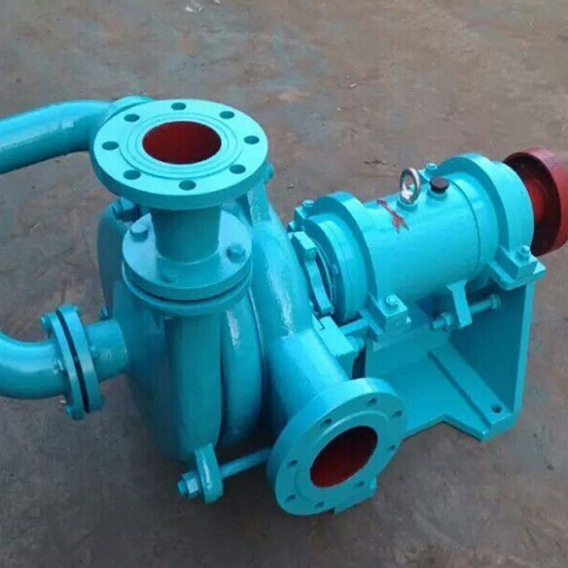
Slurry Pump Diagram: Engineering Analysis and Performance Specifications
A slurry pump is a specialized centrifugal pump designed to transport fluids containing high concentrations of suspended solid particles, known as slurries. In the industrial chain, these pumps serve as the critical conduit between extraction and processing in mining, dredging, and chemical manufacturing. The technical architecture of a slurry pump, as detailed in a comprehensive slurry pump diagram, focuses on mitigating the extreme abrasive and corrosive forces exerted by particulate matter. Unlike clean-water pumps, slurry pumps must manage non-Newtonian fluid dynamics and varying specific gravities. The core performance is measured by the pump's ability to maintain a constant volumetric flow rate while resisting the erosive wear of the impeller and volute, ensuring systemic stability in high-head and high-pressure industrial applications.
Material Science & Manufacturing
The manufacturing of slurry pumps is dictated by the principles of tribology and material science, focusing on the trade-off between hardness and toughness. The internal wetted components—primarily the impeller and the liner—are engineered from advanced materials to combat abrasive wear. High-chrome white irons (typically 27% Cr) are utilized for their exceptional hardness and resistance to scouring. For highly acidic or corrosive slurries, duplex stainless steels or natural rubber liners are employed, providing a resilient surface that absorbs particle impact rather than eroding. The rubber liners utilize a high-molecular-weight elastomer that creates a sacrificial layer, preventing the structural casing from degradation.
The manufacturing process involves precision casting and rigorous machining. The impeller is typically produced via centrifugal casting to ensure a dense, pore-free metallurgical structure, which is essential for maintaining balance at high rotational speeds. The volute casing undergoes a specialized heat treatment process to achieve a uniform martensitic structure, enhancing its resistance to pitting. Key parameter control during production focuses on the "clearance gap" between the impeller and the wear plate; an overly wide gap leads to internal recirculation and efficiency loss, while a gap too narrow risks catastrophic seizure if large particles enter the pump. Final assembly includes dynamic balancing of the rotating assembly to minimize vibration and extend the bearing life cycle.
Performance & Engineering
Engineering a slurry pump requires a deep analysis of the fluid's rheology and the kinematics of particle impact. The primary engineering challenge is managing the "Critical Settling Velocity"—the minimum velocity required to keep solids in suspension to prevent pipe blockage (plugging). A slurry pump diagram reveals the strategic design of the impeller vanes, which are shaped to minimize turbulence and avoid "dead zones" where solids could accumulate and cause localized erosion.
Force analysis is applied to the shaft and bearings to handle the radial loads generated by unbalanced slurry flow. The use of an expeller or an inducer is often engineered into the suction side to prevent cavitation, which is exacerbated by the presence of solids. Environmental resistance is achieved through specialized sealing mechanisms; the "gland seal" or "mechanical seal" is often flushed with clean water to prevent abrasive particles from migrating into the bearing housing. Furthermore, compliance with international engineering standards ensures that the pump can operate under variable specific gravity conditions (typically ranging from 1.1 to 1.5 SG) without experiencing premature fatigue failure or hydraulic instability.
Technical Specifications
| Performance Parameter | Low-Density Slurry (1.1 SG) | Medium-Density Slurry (1.3 SG) | High-Density Slurry (1.5 SG) | Extreme-Density Slurry (1.8 SG) |
|---|---|---|---|---|
| Maximum Flow Rate (m³/h) | 1200 | 1000 | 800 | 600 |
| Total Dynamic Head (m) | 45 | 40 | 35 | 30 |
| Impeller Material | Natural Rubber | High Chrome Alloy | High Chrome Alloy | Ceramic Composite |
| Efficiency (%) | 82% | 78% | 72% | 65% |
| Allowable Solid Size (mm) | 15 | 25 | 35 | 50 |
| Shaft Power Requirement (kW) | 110 | 132 | 160 | 200 |
Failure Mode & Maintenance
Failure analysis in slurry pumps typically identifies three primary modes: erosive wear, cavitation-induced pitting, and mechanical seal failure. Erosive wear occurs when high-velocity particles strike the impeller vanes and volute walls, leading to "thinning" of the material. This results in a drop in pump efficiency and an increase in internal recirculation. Cavitation occurs when the Net Positive Suction Head available (NPSHa) falls below the required (NPSHr), creating vapor bubbles that collapse violently, causing micro-fractures in the metal surface.
To mitigate these failures, a professional maintenance regime must be implemented. This includes the installation of wear-monitoring sensors to track the thickness of the liner. When the liner reaches a critical wear limit, it must be replaced to prevent the slurry from attacking the outer structural shell. For mechanical failures, vibration analysis is used to detect misalignment or bearing fatigue before catastrophic failure occurs. Lubrication systems must be monitored for contamination; the presence of slurry particles in the oil indicates a breach in the sealing system, requiring immediate replacement of the gland packing or mechanical seals to prevent shaft scoring.
Industry FAQ
Q: How does the specific gravity (SG) of the slurry affect the power requirements of the pump?
A: Power consumption is directly proportional to the density of the fluid. As the SG increases, the mass flow rate for a given volume increases, requiring higher torque from the motor to maintain the same rotational speed and head. Engineers must oversize the motor to account for the maximum possible SG to avoid overloading.
Q: Which is more effective for abrasive slurries: high-chrome alloys or rubber liners?
A: It depends on the particle size and hardness. High-chrome alloys are superior for large, sharp, and hard particles that would cut through rubber. Rubber liners are more effective for fine, sandy particles where the material's elasticity allows the particles to "bounce" off the surface rather than abrade it.
Q: What is the primary cause of premature impeller failure in high-head applications?
A: The primary cause is typically "impeller cavitation" combined with high-velocity erosion. In high-head scenarios, the fluid velocity at the impeller tip is extreme; if the suction is insufficient, cavitation bubbles form and collapse, stripping the protective oxide layer from the metal and accelerating abrasive wear.
Q: How often should the wear plates be inspected and replaced?
A: Inspection intervals depend on the slurry concentration and abrasiveness. In high-load mining operations, ultrasonic thickness testing is recommended every 500 to 1,000 operating hours. Replacement should occur when the liner thickness reaches 20% of its original value to protect the pump casing.
Q: Can a standard centrifugal pump be modified for slurry use?
A: Generally, no. Standard pumps lack the necessary material hardness, specialized seal designs, and wide-clearance impellers required for solids. Modifying a clean-water pump usually leads to rapid failure due to clogging, seal leakage, and rapid erosive wear of the thin-walled casting.
Conclusion
The operational efficiency of a slurry pump is fundamentally dependent on the synergy between material selection and hydraulic design. By analyzing the slurry pump diagram through the lens of fluid dynamics and metallurgy, it becomes evident that managing the interplay between particle velocity, material hardness, and system pressure is the only way to ensure long-term reliability in harsh industrial environments.
Looking forward, the integration of smart sensors for real-time wear monitoring and the development of nano-composite ceramics will further extend the service life of these critical components. For procurement managers and engineers, prioritizing the Total Cost of Ownership (TCO) over initial capital expenditure—by focusing on high-grade materials and precise engineering specifications—remains the most sustainable strategy for slurry transport systems.
-
Comprehensive Guide to Waterproof ORings for Optimal Sealing Solutions
News2026-06-09
-
septic system sump pump Performance Analysis
News2026-06-26
-
septic pump company Performance Analysis
News2026-06-26
-
pumps water treatment Performance Analysis
News2026-06-26
-
pumps for septic tanks Material Science and Manufacturing
News2026-06-26
-
pump for septic system Material Science Manufacturing
News2026-06-26
-
heavy duty submersible pump Performance Analysis
News2026-06-25
-
best submersible pump for septic tank Performance Analysis
News2026-06-25
-
basement sewer ejector pump Performance Analysis
News2026-06-25
-
basement pumps ejector pumps Performance Analysis
News2026-06-25
-
basement lift pump Performance and Engineering
News2026-06-25
-
basement bathroom pump systems Performance Analysis
News2026-06-24
-
basement bathroom ejector pump system Performance Engineering
News2026-06-24
-
2 hp sewage pump Performance Engineering
News2026-06-24
-
1 hp septic pump Performance Engineering
News2026-06-24


