English
- Afrikaans
- Albanian
- Amharic
- Arabic
- Armenian
- Azerbaijani
- Basque
- Belarusian
- Bengali
- Bosnian
- Bulgarian
- Catalan
- Cebuano
- Corsican
- Croatian
- Czech
- Danish
- Dutch
- English
- Esperanto
- Estonian
- Finnish
- French
- Frisian
- Galician
- Georgian
- German
- Greek
- Gujarati
- Haitian Creole
- hausa
- hawaiian
- Hebrew
- Hindi
- Miao
- Hungarian
- Icelandic
- igbo
- Indonesian
- irish
- Italian
- Japanese
- Javanese
- Kannada
- kazakh
- Khmer
- Rwandese
- Korean
- Kurdish
- Kyrgyz
- Lao
- Latin
- Latvian
- Lithuanian
- Luxembourgish
- Macedonian
- Malgashi
- Malay
- Malayalam
- Maltese
- Maori
- Marathi
- Mongolian
- Myanmar
- Nepali
- Norwegian
- Norwegian
- Occitan
- Pashto
- Persian
- Polish
- Portuguese
- Punjabi
- Romanian
- Russian
- Samoan
- Scottish Gaelic
- Serbian
- Sesotho
- Shona
- Sindhi
- Sinhala
- Slovak
- Slovenian
- Somali
- Spanish
- Sundanese
- Swahili
- Swedish
- Tagalog
- Tajik
- Tamil
- Tatar
- Telugu
- Thai
- Turkish
- Turkmen
- Ukrainian
- Urdu
- Uighur
- Uzbek
- Vietnamese
- Welsh
- Bantu
- Yiddish
- Yoruba
- Zulu
 Co., Ltd.")
Telephone: +86 13120555503
Email: frank@cypump.com


Apr . 01, 2024 17:55 Back to list
slurry jet pump Manufacturing Specification and Performance Analysis
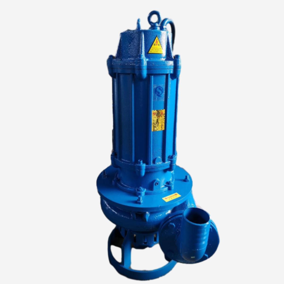
Slurry Jet Pump Manufacturing Specification and Performance Analysis
A slurry jet pump is a specialized hydraulic device designed to transport high-density, abrasive fluids—consisting of solid particles suspended in a liquid medium—without the use of internal moving parts. Positioned as a critical component in the mid-stream and down-stream processing of mining, dredging, and chemical industries, the jet pump operates on the Venturi principle. By utilizing a high-pressure motive fluid (driving fluid) injected through a nozzle, a low-pressure zone is created at the suction throat, effectively drawing in the slurry and accelerating it through a diffuser. Unlike centrifugal pumps, the absence of an impeller eliminates the risk of mechanical seizure due to oversized particulates, making it the primary technical solution for deep-well desanding, tailings management, and the transport of caustic, high-viscosity industrial waste. Its technical value lies in its ability to maintain consistent volumetric flow rates while mitigating the catastrophic wear typically associated with high-velocity particulate impingement.
Material Science & Manufacturing
The operational environment of a slurry jet pump is characterized by extreme erosive wear and chemical corrosion. Consequently, material selection focuses on maximizing the Hardness-to-Toughness ratio. The primary structural components are typically fabricated from High-Chromium Cast Iron (ASTM A532), which contains 12% to 28% Chromium to form a hard eutectic carbide network within a martensitic matrix, providing superior resistance to abrasive sliding. For applications involving acidic or saline slurries, Duplex Stainless Steel (ASTM A890) or Nickel-Alloy cladding is employed to prevent pitting and stress corrosion cracking (SCC).
The manufacturing process begins with precision investment casting to ensure the internal geometry of the nozzle and diffuser adheres to strict fluid dynamic tolerances. Any deviation in the nozzle orifice diameter can lead to turbulent flow and premature cavitation. Post-casting, components undergo a rigorous heat treatment cycle—including austenitizing and quenching—to achieve a Rockwell hardness (HRC) exceeding 58. The critical internal surfaces are then finished using CNC grinding and diamond polishing to reduce surface roughness (Ra < 0.8 μm), thereby minimizing the boundary layer friction and reducing the onset of erosion-corrosion. The final assembly utilizes precision-machined flange joints with PTFE or Viton gaskets to ensure hermetic sealing against high-pressure motive fluid leaks.
Performance & Engineering
Engineering a slurry jet pump requires an intricate balance of the Motive Fluid Pressure (P1) and the Suction Pressure (P2). The performance is governed by the "Jet Pump Ratio," which defines the relationship between the motive flow rate and the suction flow rate. From a force analysis perspective, the pump converts the kinetic energy of the high-velocity jet into potential energy (pressure) in the diffuser section. The engineering challenge resides in the "Mixing Zone," where the high-velocity motive stream entrains the slower slurry. If the velocity gradient is too steep, the resultant shear stress can lead to particle attrition or the degradation of sensitive chemical polymers within the slurry.
Environmental resistance is managed through the implementation of thick-walled pressure vessels capable of withstanding transient pressure surges (water hammer). Compliance with hydraulic efficiency standards requires the optimization of the diffuser angle; an angle that is too wide leads to flow separation and energy loss, while an angle that is too narrow increases the risk of clogging by oversized particles. Furthermore, the pump must be engineered to handle non-Newtonian fluid behavior, specifically Bingham plastics or pseudoplastic slurries, where the apparent viscosity changes based on the shear rate. This requires the calculation of the Reynolds number for non-Newtonian fluids to ensure the pump operates within a stable turbulent regime, preventing the settling of solids within the pump body.
Technical Specifications
| Specification Parameter | Standard Grade (Chrome Steel) | Heavy Duty (Tungsten Carbide) | Corrosion Resistant (Duplex) | Ultra-High Pressure (Special Alloy) |
|---|---|---|---|---|
| Max Motive Pressure (MPa) | 15 - 25 | 25 - 40 | 10 - 20 | 40 - 70 |
| Suction Capacity (m³/h) | 50 - 200 | 100 - 500 | 30 - 150 | 200 - 800 |
| Max Particle Size (mm) | 5 - 10 | 10 - 25 | 2 - 8 | 15 - 30 |
| Erosion Rate (mm/1000h) | 0.4 - 0.8 | 0.1 - 0.3 | 0.6 - 1.2 | 0.2 - 0.5 |
| Operating Temp Range (°C) | -20 to 120 | -40 to 300 | -20 to 150 | -50 to 450 |
| Material Hardness (HRC) | 55 - 62 | 70 - 85 | 30 - 45 | 60 - 75 |
Failure Mode & Maintenance
Failure analysis of slurry jet pumps typically reveals three primary failure modes: Cavitation Erosion, Abrasive Thinning, and Galvanic Corrosion. Cavitation occurs when the local pressure in the suction throat drops below the vapor pressure of the liquid, forming bubbles that implode violently upon entering the diffuser, causing "pitting" on the internal walls. Abrasive thinning is a gradual loss of material, primarily concentrated at the nozzle exit and the throat of the diffuser, where fluid velocities are highest. This leads to a decrease in the pressure recovery efficiency and a subsequent drop in the suction lift capacity.
To mitigate these failures, a professional maintenance protocol must be established. First, a scheduled Ultrasonic Thickness Testing (UT) should be performed every 500 operating hours to monitor wall thinning in the high-velocity zones. When the wall thickness reaches 70% of the original specification, the nozzle insert must be replaced. For cavitation prevention, the motive pressure must be regulated via a Variable Frequency Drive (VFD) to ensure the pump does not operate far from its Best Efficiency Point (BEP). Maintenance also involves the periodic flushing of the system with clean water to remove stagnant slurry deposits that could cause localized under-deposit corrosion. Finally, for chemical-heavy applications, the installation of sacrificial anodes or the use of cathodic protection is recommended to prevent the degradation of the primary alloy structure.
Industry FAQ
Q: How does a jet pump handle varying slurry concentrations compared to centrifugal pumps?
A: Centrifugal pumps suffer from significant efficiency drops and impeller wear as the solid concentration increases. In contrast, a slurry jet pump maintains a more stable flow because it has no rotating parts in contact with the slurry. Its performance is primarily dependent on the motive fluid's energy, allowing it to transport higher solids-to-liquid ratios without risking mechanical failure.
Q: What is the primary cause of a sudden drop in suction lift in a jet pump system?
A: The most common cause is nozzle erosion or partial blockage. Even a minor increase in the nozzle diameter due to wear reduces the exit velocity of the motive fluid, which weakens the Venturi effect and increases the pressure in the suction throat, thereby reducing the pump's ability to lift the slurry.
Q: Which material is more suitable for a slurry containing both high acidity and high abrasive quartz?
A: In such hybrid environments, standard High-Chrome steel may fail due to acid attack. The recommended solution is a Duplex Stainless Steel body with Tungsten Carbide liners in the nozzle and diffuser sections. This combines the chemical resistance of the Duplex alloy with the extreme hardness of the carbide to resist quartz abrasion.
Q: Can a slurry jet pump be used for high-viscosity non-Newtonian fluids?
A: Yes, but it requires a redesign of the diffuser angle and a higher motive pressure. High-viscosity fluids increase the frictional head loss; therefore, the motive jet must provide sufficient kinetic energy to overcome the yield stress of the fluid and maintain a turbulent flow to keep particles in suspension.
Q: How do we determine the optimal motive-to-suction flow ratio?
A: The optimal ratio is determined through hydraulic modeling based on the desired suction lift and the density of the slurry. Typically, a ratio of 1:1 to 1:4 is used, but this must be validated through a performance curve analysis to ensure the pump operates at the maximum volumetric efficiency without inducing cavitation.
Conclusion
The slurry jet pump represents a sophisticated application of fluid dynamics and material science, offering a robust alternative to mechanical pumping systems in the most demanding industrial environments. By eliminating internal moving parts and leveraging the Venturi effect, it effectively solves the industry pain points of mechanical wear and frequent downtime associated with abrasive slurry transport. The technical integrity of the system depends entirely on the precision of the nozzle geometry and the selection of wear-resistant alloys.
Looking forward, the integration of real-time erosion monitoring sensors and the adoption of additive manufacturing for complex internal diffuser geometries will further enhance the efficiency of these systems. For procurement and engineering teams, the focus must remain on matching the material specifications to the specific chemical and abrasive profile of the slurry to maximize the lifecycle and operational reliability of the installation.
-
Comprehensive Guide to Waterproof ORings for Optimal Sealing Solutions
News2026-06-09
-
heavy duty submersible pump Performance Analysis
News2026-06-25
-
best submersible pump for septic tank Performance Analysis
News2026-06-25
-
basement sewer ejector pump Performance Analysis
News2026-06-25
-
basement pumps ejector pumps Performance Analysis
News2026-06-25
-
basement lift pump Performance and Engineering
News2026-06-25
-
basement bathroom pump systems Performance Analysis
News2026-06-24
-
basement bathroom ejector pump system Performance Engineering
News2026-06-24
-
2 hp sewage pump Performance Engineering
News2026-06-24
-
1 hp septic pump Performance Engineering
News2026-06-24
-
submersible effluent pump Performance Analysis
News2026-06-24
-
submergable pump Material Science
News2026-06-23
-
sewer injection pump Performance Engineering
News2026-06-23
-
Sewer Ejector Pump System Performance Analysis
News2026-06-23
-
septic tank pump for sale Performance Engineering
News2026-06-23


