English
- Afrikaans
- Albanian
- Amharic
- Arabic
- Armenian
- Azerbaijani
- Basque
- Belarusian
- Bengali
- Bosnian
- Bulgarian
- Catalan
- Cebuano
- Corsican
- Croatian
- Czech
- Danish
- Dutch
- English
- Esperanto
- Estonian
- Finnish
- French
- Frisian
- Galician
- Georgian
- German
- Greek
- Gujarati
- Haitian Creole
- hausa
- hawaiian
- Hebrew
- Hindi
- Miao
- Hungarian
- Icelandic
- igbo
- Indonesian
- irish
- Italian
- Japanese
- Javanese
- Kannada
- kazakh
- Khmer
- Rwandese
- Korean
- Kurdish
- Kyrgyz
- Lao
- Latin
- Latvian
- Lithuanian
- Luxembourgish
- Macedonian
- Malgashi
- Malay
- Malayalam
- Maltese
- Maori
- Marathi
- Mongolian
- Myanmar
- Nepali
- Norwegian
- Norwegian
- Occitan
- Pashto
- Persian
- Polish
- Portuguese
- Punjabi
- Romanian
- Russian
- Samoan
- Scottish Gaelic
- Serbian
- Sesotho
- Shona
- Sindhi
- Sinhala
- Slovak
- Slovenian
- Somali
- Spanish
- Sundanese
- Swahili
- Swedish
- Tagalog
- Tajik
- Tamil
- Tatar
- Telugu
- Thai
- Turkish
- Turkmen
- Ukrainian
- Urdu
- Uighur
- Uzbek
- Vietnamese
- Welsh
- Bantu
- Yiddish
- Yoruba
- Zulu
 Co., Ltd.")
Telephone: +86 13120555503
Email: frank@cypump.com


Apr . 01, 2024 17:55 Back to list
self priming slurry pump Performance Analysis and Manufacturing Specifications
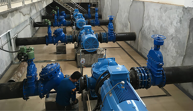
Self Priming Slurry Pump Performance Analysis and Manufacturing Specifications
A self-priming slurry pump is a specialized centrifugal machine designed to evacuate air from the suction line and transport abrasive, high-density fluids—consisting of solid particles suspended in a liquid medium—without the need for an external priming system or a foot valve. Within the industrial value chain, these pumps occupy a critical position in mineral processing, dredging, waste treatment, and chemical manufacturing. Unlike standard centrifugal pumps, which lose prime if air enters the casing, the self-priming slurry pump utilizes a unique hydraulic recirculation mechanism. By maintaining a reservoir of liquid within the casing, the pump creates a partial vacuum that draws the slurry from the source. The core performance of these units is measured by their ability to maintain high volumetric efficiency while resisting the extreme erosive wear caused by high-velocity particulate impingement and the corrosive nature of chemical slurries.
Material Science & Manufacturing
The manufacturing of self-priming slurry pumps focuses on the mitigation of abrasive wear and cavitation. The material selection is governed by the Mohs hardness of the transported solids and the pH level of the carrier fluid. For high-chrome applications, ASTM A532 Class III Type A high-chromium white iron is frequently employed due to its exceptional hardness (up to 65 HRC), providing a robust defense against scouring. In environments where corrosion outweighs abrasion, duplex stainless steels or CD4MCu are utilized to prevent pitting and stress corrosion cracking.
The manufacturing process begins with high-precision casting of the impeller and volute. Advanced investment casting or sand casting is used to ensure a dense metallurgical structure, minimizing porosity that could lead to premature failure under high-pressure cycles. The impeller is typically a semi-open design to prevent clogging by large solids; it undergoes dynamic balancing to ISO 1940 G2.5 standards to reduce vibration-induced fatigue. Key parameter control during manufacturing includes the machining of the wear plate clearances—typically maintained within a strict tolerance of 0.3mm to 0.5mm—to prevent internal recirculation and maximize suction lift. Furthermore, the casing is often reinforced with thick-walled sections in high-velocity zones, and the internal surfaces are polished to reduce fluid friction and energy loss during the priming phase.
Performance & Engineering
Engineering a self-priming slurry pump requires a complex force analysis of the fluid-solid interaction. The primary challenge is managing the "critical velocity"—the minimum speed at which solids remain suspended in the fluid to prevent sedimentation within the pump casing. If the flow velocity drops below this threshold, solids settle, leading to blockage and catastrophic pump failure. Engineers calculate the slurry density (specific gravity) and particle size distribution to determine the optimal impeller diameter and rotational speed (RPM).
The self-priming mechanism operates on a hydraulic circuit where a portion of the pumped fluid is diverted back to the suction side to displace air. This requires a precise volumetric balance to ensure that the vacuum is sufficient to overcome the Net Positive Suction Head (NPSHr) requirements. Environmental resistance is achieved through the implementation of heavy-duty mechanical seals or specialized gland packing, often featuring a flushing system to prevent slurry from entering the seal faces. Compliance with international pressure vessel standards ensures that the casing can withstand the surge pressures associated with the transition from air-pumping to liquid-pumping, a phase characterized by sudden torque spikes and hydraulic shocks.
Technical Specifications
| Performance Parameter | Standard Slurry Unit | High-Density Unit | Heavy-Duty Unit |
|---|---|---|---|
| Max Flow Rate (m³/h) | 120 | 250 | 500 |
| Max Discharge Head (m) | 35 | 50 | 80 |
| Max Particle Size (mm) | 15 | 30 | 60 |
| Casing Material | High-Chrome Iron | Duplex Steel | High-Chrome Alloy |
| Priming Time (s) | 45 - 90 | 60 - 120 | 90 - 180 |
| Operating Temp Range (°C) | -10 to 80 | -20 to 110 | -20 to 150 |
Failure Mode & Maintenance
Failure analysis of self-priming slurry pumps typically identifies three primary modes: erosive wear, cavitation, and seal degradation. Erosive wear occurs primarily at the impeller vanes and the volute tongue, where high-velocity slurry impingement strips the material surface. This manifests as a gradual decline in head and flow rate. Cavitation occurs when the local pressure drops below the vapor pressure of the liquid, creating bubbles that collapse violently against the metal surfaces, causing "pitting" or a sponge-like surface texture. Delamination can also occur in coated components if the chemical compatibility between the slurry and the coating is compromised.
Professional maintenance requires a predictive approach. Vibration analysis is used to detect impeller imbalance or bearing wear before failure. The wear plate must be inspected monthly; once the clearance exceeds 1.5mm, the pump's priming efficiency drops significantly, and it must be replaced. For mechanical seals, a rigorous flushing regimen using clean water is mandatory to prevent abrasive particles from scoring the seal faces. When replacing components, it is critical to ensure that the new impeller is balanced and that the casing is flushed to remove any residual solids that could cause mechanical interference during startup.
Industry FAQ
Q: What is the primary cause of a self-priming slurry pump failing to prime?
A: The most common cause is an air leak in the suction piping or a failure of the casing seal. Since the pump relies on creating a partial vacuum to lift the slurry, even a microscopic breach in the suction line allows air to enter, breaking the vacuum and preventing the fluid from reaching the impeller.
Q: How do you determine the correct material for the pump impeller based on the slurry type?
A: Selection is based on the "Abrasion-Corrosion" matrix. For highly abrasive but non-corrosive slurries (e.g., silica sand), high-chromium white iron is preferred. For corrosive slurries with low solids (e.g., chemical waste), 316L or Duplex stainless steel is used. For combined environments, specialized alloys like CD4MCu provide a balance of hardness and chemical resistance.
Q: Why is the "Critical Velocity" so important in slurry pump engineering?
A: If the flow velocity falls below the critical velocity, the solid particles in the slurry will settle due to gravity. This leads to "sanding" or sediment build-up in the pump casing and discharge pipes, which increases friction, reduces flow, and can eventually lead to a complete blockage or motor overload.
Q: Can these pumps handle high concentrations of air mixed with the slurry?
A: While self-priming pumps are designed to evacuate air initially, a continuous high concentration of air (air-entrainment) in the slurry will lead to "air locking." This reduces the pump's efficiency and can cause severe vibration and cavitation-like damage to the impeller.
Q: What is the recommended maintenance interval for the wear plates?
A: Maintenance intervals depend on the slurry's abrasiveness. In high-grit mining applications, wear plates should be inspected every 200-500 operating hours. In lighter applications, quarterly inspections are usually sufficient. Replacement is triggered when the gap between the impeller and the plate exceeds the engineering limit of 1.5mm.
Conclusion
The self-priming slurry pump is a sophisticated engineering solution that balances the conflicting requirements of vacuum generation and abrasive material transport. By integrating advanced material science—specifically the use of high-chromium alloys—with precise hydraulic design, these pumps ensure operational continuity in the most demanding industrial environments. The technical integrity of the system relies on the strict control of clearances and the maintenance of critical flow velocities to prevent sedimentation.
Looking forward, the industry is moving toward the integration of IoT-based condition monitoring to predict wear patterns in real-time, reducing unplanned downtime. It is recommended that operators prioritize the alignment of NPSH requirements and implement rigorous seal flushing protocols to maximize the lifecycle of the equipment. Ultimately, the synergy between robust metallurgical selection and precise operational parameter control is the only way to ensure the reliability of slurry transport systems.
-
Comprehensive Guide to Waterproof ORings for Optimal Sealing Solutions
News2026-06-09
-
heavy duty submersible pump Performance Analysis
News2026-06-25
-
best submersible pump for septic tank Performance Analysis
News2026-06-25
-
basement sewer ejector pump Performance Analysis
News2026-06-25
-
basement pumps ejector pumps Performance Analysis
News2026-06-25
-
basement lift pump Performance and Engineering
News2026-06-25
-
basement bathroom pump systems Performance Analysis
News2026-06-24
-
basement bathroom ejector pump system Performance Engineering
News2026-06-24
-
2 hp sewage pump Performance Engineering
News2026-06-24
-
1 hp septic pump Performance Engineering
News2026-06-24
-
submersible effluent pump Performance Analysis
News2026-06-24
-
submergable pump Material Science
News2026-06-23
-
sewer injection pump Performance Engineering
News2026-06-23
-
Sewer Ejector Pump System Performance Analysis
News2026-06-23
-
septic tank pump for sale Performance Engineering
News2026-06-23


