English
- Afrikaans
- Albanian
- Amharic
- Arabic
- Armenian
- Azerbaijani
- Basque
- Belarusian
- Bengali
- Bosnian
- Bulgarian
- Catalan
- Cebuano
- Corsican
- Croatian
- Czech
- Danish
- Dutch
- English
- Esperanto
- Estonian
- Finnish
- French
- Frisian
- Galician
- Georgian
- German
- Greek
- Gujarati
- Haitian Creole
- hausa
- hawaiian
- Hebrew
- Hindi
- Miao
- Hungarian
- Icelandic
- igbo
- Indonesian
- irish
- Italian
- Japanese
- Javanese
- Kannada
- kazakh
- Khmer
- Rwandese
- Korean
- Kurdish
- Kyrgyz
- Lao
- Latin
- Latvian
- Lithuanian
- Luxembourgish
- Macedonian
- Malgashi
- Malay
- Malayalam
- Maltese
- Maori
- Marathi
- Mongolian
- Myanmar
- Nepali
- Norwegian
- Norwegian
- Occitan
- Pashto
- Persian
- Polish
- Portuguese
- Punjabi
- Romanian
- Russian
- Samoan
- Scottish Gaelic
- Serbian
- Sesotho
- Shona
- Sindhi
- Sinhala
- Slovak
- Slovenian
- Somali
- Spanish
- Sundanese
- Swahili
- Swedish
- Tagalog
- Tajik
- Tamil
- Tatar
- Telugu
- Thai
- Turkish
- Turkmen
- Ukrainian
- Urdu
- Uighur
- Uzbek
- Vietnamese
- Welsh
- Bantu
- Yiddish
- Yoruba
- Zulu
 Co., Ltd.")
Telephone: +86 13120555503
Email: frank@cypump.com


Apr . 01, 2024 17:55 Back to list
rubber slurry pump Manufacturing Specification and Performance Analysis
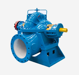
Rubber Slurry Pump Manufacturing Specification and Performance Analysis
A rubber slurry pump is a specialized heavy-duty centrifugal pumping system engineered to transport highly abrasive, non-Newtonian fluids containing suspended solid particles. Positioned as a critical asset in the midstream processing of mining, dredging, and chemical waste management, these pumps act as the primary kinetic energy transfer mechanism for transporting mineral tailings, ore slurries, and acidic waste. Unlike standard water pumps, the rubber slurry pump is defined by its ability to mitigate the synergistic effects of abrasive wear and corrosive chemical attack. Its technical position in the industrial chain is focused on maximizing the Mean Time Between Failure (MTBF) while maintaining high volumetric efficiency under extreme solids concentrations, ensuring that production throughput remains consistent despite the degenerative nature of the transported medium.
Material Science & Manufacturing
The structural integrity of a rubber slurry pump relies on the precise application of elastomer science and metallurgical bonding. The primary wetted components are typically constructed from high-grade Natural Rubber (NR) or Synthetic Elastomers (such as Nitrile or Neoprene), depending on the chemical compatibility requirements of the slurry. Natural rubber is preferred for its exceptional resilience and high tear strength, which allows the pump liner to absorb the kinetic energy of impacting particles rather than suffering surface fracture.
Manufacturing begins with the vulcanization process, where the rubber compound is heated under pressure to create cross-links between polymer chains, enhancing thermal stability and elasticity. To prevent the rubber from separating from the structural outer shell under high-pressure conditions, a specialized bonding agent is applied to the cast-iron or steel casing. The casing itself is usually fabricated from ASTM A48 Class 30 or 35 gray iron to provide the necessary rigid support and vibration damping. Key parameter control during manufacturing focuses on the "Shore A Hardness" of the rubber; a hardness range of 50-70 Shore A is typically targeted to balance the trade-off between wear resistance and the ability to deflect larger solids. Furthermore, the impeller is often engineered as a composite structure, combining a high-chrome alloy core for structural rigidity with a rubberized coating to minimize erosive wear at the vane tips.
Performance & Engineering
Engineering a rubber slurry pump requires a complex force analysis centered on fluid dynamics and particle kinetics. The primary engineering challenge is the management of "velocity-induced erosion." Since the rate of material loss is proportional to the cube of the fluid velocity, engineers utilize Computational Fluid Dynamics (CFD) to optimize the volute geometry, ensuring a smooth transition of fluid from the impeller to the discharge flange to minimize turbulence and localized high-velocity zones.
Environmental resistance is critical; the pump must operate within specific temperature envelopes to avoid the "glass transition" of the elastomer, which would lead to brittleness and immediate cracking. Compliance requirements involve strict adherence to NPSH (Net Positive Suction Head) calculations to prevent cavitation. In slurry applications, cavitation is exacerbated by the presence of solids, which can create "micro-jets" that penetrate the rubber liner. To counter this, engineers implement oversized suction inlets and optimize impeller eye diameters to reduce intake velocity. Additionally, the shaft assembly is engineered with heavy-duty bearings and specialized mechanical seals or gland packing systems designed to withstand the infiltration of abrasive fines, preventing the degradation of the drive-train components.
Technical Specifications
| Technical Parameter | Standard Specification | High-Performance Range | Industrial Tolerance | Testing Standard |
|---|---|---|---|---|
| Max Flow Rate (m³/h) | 150 - 500 | Up to 1,200 | ± 5% | ISO 9906 |
| Max Total Head (m) | 10 - 60 | Up to 110 | ± 2% | HI 14.6 |
| Max Particle Size (mm) | 5 - 20 | Up to 50 | + 1mm / - 0mm | ASTM G75 |
| Liner Hardness (Shore A) | 55 - 65 | 40 - 80 (Custom) | ± 3 Shore A | ASTM D2240 |
| Max Slurry Density (g/cm³) | 1.1 - 1.4 | Up to 1.8 | ± 0.05 | ISO 1165 |
| Operating Temp (°C) | -10 to +60 | -20 to +90 | ± 2°C | EN 10204 |
Failure Mode & Maintenance
The failure modes of rubber slurry pumps are predominantly linked to the degradation of the elastomeric interface and the mechanical fatigue of the rotating assembly. A primary failure mode is "abrasive delamination," where high-velocity particles carve channels into the rubber liner, eventually exposing the metal casing. This is often accelerated by "slugging," where an unexpected surge of high-density solids creates an impact force that exceeds the rubber's elastic limit, leading to tearing.
Another critical failure mode is "chemical degradation" or swelling. If the pump is used with fluids exceeding the chemical compatibility of the elastomer (e.g., using natural rubber for oil-based slurries), the polymer chains break down, resulting in a loss of hardness and rapid wear. Mechanical failures often manifest as shaft deflection or bearing seizure due to the infiltration of abrasive fines through the seal. Maintenance protocols must include scheduled ultrasonic thickness testing of the liners to predict the end-of-life before casing penetration occurs. Professional maintenance involves the precise alignment of the motor and pump shaft using laser alignment tools to reduce parasitic vibration, and the systematic replacement of wear parts based on cumulative tonnage processed rather than calendar time.
Industry FAQ
Q: How do we determine whether to use a rubber-lined pump or a high-chrome alloy pump for a specific slurry?
A: The decision is based on the particle size and hardness. Rubber is superior for fine to medium-sized particles (usually < 2mm) because it absorbs the energy of the impact. High-chrome alloys are necessary for coarse, large-diameter particles or high-temperature slurries where rubber would either be shredded or thermally degraded.
Q: What is the primary cause of premature liner failure in new installations?
A: The most common cause is running the pump "dry" or with a fluid that is too thin. Rubber liners require the presence of a fluid medium to dissipate heat; without it, friction creates localized hotspots that cause the rubber to harden, crack, and eventually peel away from the casing.
Q: How does the concentration of solids affect the NPSH requirements?
A: Increasing the solids concentration increases the viscosity and the density of the fluid, which elevates the frictional losses in the suction piping. This reduces the available NPSH, increasing the risk of cavitation. We recommend increasing the suction pipe diameter and minimizing bends to compensate.
Q: Can rubber slurry pumps handle acidic materials?
A: Yes, provided the elastomer is correctly selected. Natural rubber has good resistance to many dilute acids, but for highly aggressive chemical slurries, we specify chloroprene or EPDM liners to prevent chemical oxidation and swelling.
Q: What are the indicators that the impeller is nearing the end of its service life?
A: The primary indicators are a gradual decrease in discharge pressure and a drop in flow rate (volumetric efficiency) while the motor amperage remains constant or slightly decreases. This indicates that the impeller vanes have worn down, increasing the internal recirculation (slip).
Conclusion
The operational efficiency of a rubber slurry pump is fundamentally a balance between material elasticity and hydraulic precision. By integrating high-resilience elastomers with optimized volute geometries, these systems successfully mitigate the destructive forces of abrasion and corrosion. The technical success of the installation depends not only on the initial manufacturing specifications but on a rigorous understanding of the slurry's rheological properties and the subsequent adherence to predictive maintenance schedules.
Looking forward, the industry is moving toward "smart" slurry pumping, incorporating real-time wear sensors and variable frequency drives (VFDs) to optimize flow velocity based on real-time solids concentration. For procurement and engineering teams, the focus must remain on the synergy between elastomer chemistry and mechanical alignment to ensure maximum equipment longevity and minimized operational downtime in the most demanding industrial environments.
-
Comprehensive Guide to Waterproof ORings for Optimal Sealing Solutions
News2026-06-09
-
septic system sump pump Performance Analysis
News2026-06-26
-
septic pump company Performance Analysis
News2026-06-26
-
pumps water treatment Performance Analysis
News2026-06-26
-
pumps for septic tanks Material Science and Manufacturing
News2026-06-26
-
pump for septic system Material Science Manufacturing
News2026-06-26
-
heavy duty submersible pump Performance Analysis
News2026-06-25
-
best submersible pump for septic tank Performance Analysis
News2026-06-25
-
basement sewer ejector pump Performance Analysis
News2026-06-25
-
basement pumps ejector pumps Performance Analysis
News2026-06-25
-
basement lift pump Performance and Engineering
News2026-06-25
-
basement bathroom pump systems Performance Analysis
News2026-06-24
-
basement bathroom ejector pump system Performance Engineering
News2026-06-24
-
2 hp sewage pump Performance Engineering
News2026-06-24
-
1 hp septic pump Performance Engineering
News2026-06-24


