English
- Afrikaans
- Albanian
- Amharic
- Arabic
- Armenian
- Azerbaijani
- Basque
- Belarusian
- Bengali
- Bosnian
- Bulgarian
- Catalan
- Cebuano
- Corsican
- Croatian
- Czech
- Danish
- Dutch
- English
- Esperanto
- Estonian
- Finnish
- French
- Frisian
- Galician
- Georgian
- German
- Greek
- Gujarati
- Haitian Creole
- hausa
- hawaiian
- Hebrew
- Hindi
- Miao
- Hungarian
- Icelandic
- igbo
- Indonesian
- irish
- Italian
- Japanese
- Javanese
- Kannada
- kazakh
- Khmer
- Rwandese
- Korean
- Kurdish
- Kyrgyz
- Lao
- Latin
- Latvian
- Lithuanian
- Luxembourgish
- Macedonian
- Malgashi
- Malay
- Malayalam
- Maltese
- Maori
- Marathi
- Mongolian
- Myanmar
- Nepali
- Norwegian
- Norwegian
- Occitan
- Pashto
- Persian
- Polish
- Portuguese
- Punjabi
- Romanian
- Russian
- Samoan
- Scottish Gaelic
- Serbian
- Sesotho
- Shona
- Sindhi
- Sinhala
- Slovak
- Slovenian
- Somali
- Spanish
- Sundanese
- Swahili
- Swedish
- Tagalog
- Tajik
- Tamil
- Tatar
- Telugu
- Thai
- Turkish
- Turkmen
- Ukrainian
- Urdu
- Uighur
- Uzbek
- Vietnamese
- Welsh
- Bantu
- Yiddish
- Yoruba
- Zulu
 Co., Ltd.")
Telephone: +86 13120555503
Email: frank@cypump.com


Apr . 01, 2024 17:55 Back to list
mud slurry pump Performance Analysis and Manufacturing Specifications
Mud Slurry Pump Performance Analysis and Manufacturing Specifications
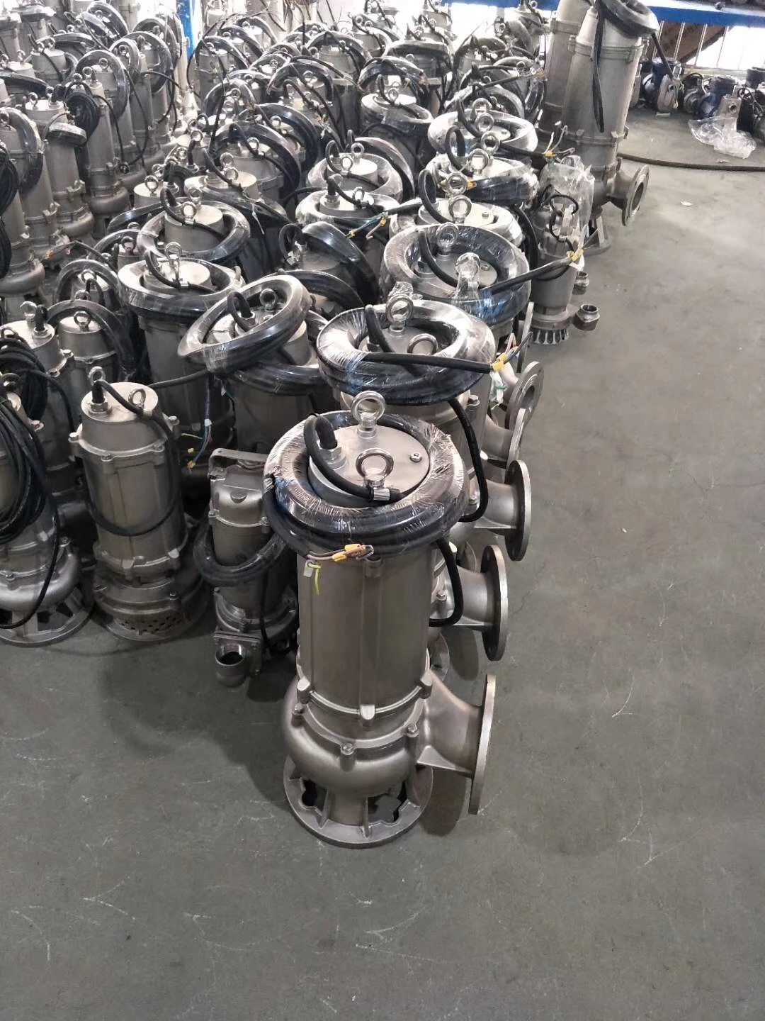
A mud slurry pump is a specialized heavy-duty hydraulic machine engineered to transport high-density fluids containing suspended solid particles, such as mineral ores, tailings, dredging silt, and chemical slurries. Positioned as a critical node in the industrial value chain—spanning mining, petrochemicals, and civil engineering—these pumps must overcome the dual challenges of extreme volumetric flow requirements and the aggressive abrasive nature of the medium. Unlike standard centrifugal pumps, mud slurry pumps are characterized by their ability to handle non-Newtonian fluids where viscosity varies with shear rate, requiring precise hydraulic design to prevent sedimentation and ensure continuous throughput. The core performance of these systems is measured by their Net Positive Suction Head (NPSH) requirements, wear-life of internal components, and the ability to maintain efficiency under fluctuating solid-to-liquid ratios.
Material Science & Manufacturing
The longevity of a mud slurry pump is fundamentally determined by the material science applied to its wetted parts. Due to the high concentration of abrasive particles (such as silica or alumina), standard cast iron or stainless steels are insufficient. Industry standards dictate the use of High-Chrome White Cast Irons (ASTM A532) and Natural Rubber liners. High-chrome alloys (typically 25% to 28% Cr) provide a hard martensitic matrix with embedded primary M7C3 carbides, offering superior resistance to sliding abrasion. Conversely, for slurries with finer particles but high impact, natural rubber or polyurethane liners are utilized to absorb kinetic energy through elastic deformation, effectively "bouncing" particles away from the pump casing.
Manufacturing processes involve precision investment casting for impellers to ensure optimal hydrodynamic profiles and minimize turbulence, which is a primary driver of localized erosion. The machining phase requires CNC grinding of the shaft and precise tolerance fitting of the mechanical seals. Key parameter control focuses on the "balance of the impeller," where dynamic balancing to G2.5 standards is mandatory to prevent vibration-induced fatigue. Furthermore, the casing undergoes heat treatment (quenching and tempering) to eliminate internal stresses and ensure a uniform hardness profile across the wall thickness, preventing premature cracking under high-pressure surges.
Performance & Engineering
Engineering a mud slurry pump requires a deep analysis of fluid dynamics and force distribution. The primary engineering challenge is the management of the "critical velocity"—the minimum velocity required to keep solids in suspension and prevent pipeline plugging. If the velocity drops below this threshold, sedimentation occurs, leading to catastrophic blockages. Engineers utilize the Durand equation to calculate these limits based on particle size, density, and fluid viscosity.
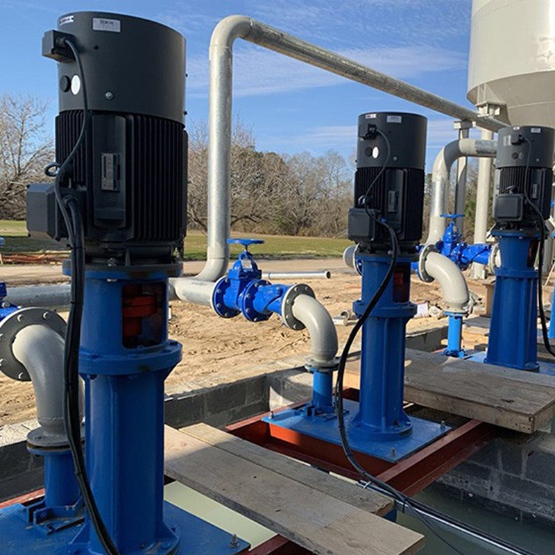
Environmental resistance is another critical factor. In mining applications, pumps often encounter acidic or alkaline slurries, necessitating the use of Duplex stainless steels or specialized coatings to prevent galvanic corrosion. The functional implementation of the pump also includes the integration of a variable frequency drive (VFD) to modulate flow rates according to the slurry density. Force analysis focuses on the radial loads exerted on the bearings; because slurry pumps often operate with asymmetric loads due to solid distribution, heavy-duty spherical roller bearings are employed to accommodate slight shaft deflections without failing.
Technical Specifications
| Specification Parameter | Standard Duty Grade | Heavy Duty Grade | Extreme Duty Grade | Tolerance/Standard |
|---|---|---|---|---|
| Max Flow Rate (m³/h) | 150 - 500 | 500 - 1200 | 1200 - 3000 | ± 5% |
| Max Discharge Head (m) | 20 - 60 | 60 - 120 | 120 - 250 | ± 3% |
| Liner Material | High Chrome Alloy | Chrome-Rubber Composite | Ceramic-Lined Steel | ASTM A532 |
| Solid Particle Size (mm) | ≤ 10 mm | ≤ 30 mm | ≤ 100 mm | D50 Distribution |
| Operating Temperature (°C) | -10 to 80 | -20 to 110 | -40 to 180 | ISO 2393 |
| Seal Type | Single Mechanical | Double Mechanical | Expeller/Seal-less | API 682 |
Failure Mode & Maintenance
Failure analysis in mud slurry pumps typically reveals four primary modes: abrasive wear, cavitation, fatigue cracking, and seal degradation. Abrasive wear occurs primarily at the impeller vane tips and the volute tongue, where fluid velocity is highest. This is characterized by "scouring" patterns. Cavitation occurs when the NPSH available is lower than the NPSH required, creating vapor bubbles that implode and pit the metal surface, often mistaken for corrosion. Fatigue cracking is usually found in the pump shaft or bearing housings, caused by excessive vibration or misalignment during installation.
Professional maintenance requires a transition from reactive to predictive strategies. Vibration analysis (using accelerometers) should be performed monthly to detect bearing wear before seizure. The "liner thickness check" is critical; ultrasonic thickness gauging allows operators to determine the remaining life of the casing without dismantling the pump. Maintenance solutions include the implementation of a flushing system for the mechanical seals to prevent slurry particles from entering the seal faces, and the use of laser alignment tools to ensure the motor and pump shafts are concentric within 0.05mm.
Industry FAQ
Q: How do we determine the optimal liner material for a specific slurry application?
A: The selection depends on the particle size and impact velocity. For fine, abrasive particles at high velocities, high-chrome alloys are preferred due to their hardness. For larger particles with high impact energy, natural rubber liners are superior as they absorb the impact rather than fracturing.
Q: Why is the pump experiencing sudden drops in discharge pressure despite constant RPM?
A: This is typically indicative of internal recirculation caused by excessive wear in the wear rings or impeller clearance. As the gap increases, fluid leaks back to the suction side, reducing the effective head and volumetric efficiency.
Q: What is the impact of slurry viscosity on the NPSH requirement?
A: Higher viscosity increases friction losses in the suction piping, which reduces the NPSH available. To compensate, you must either increase the suction pipe diameter, raise the slurry tank level, or reduce the fluid temperature to stabilize viscosity.
Q: How can we prevent "plugging" during pump startup?
A: A "water flush" or "priming" sequence is essential. The pump should be started with clean water to establish flow before the slurry valve is opened. This prevents the pump from attempting to accelerate a stagnant, settled bed of solids, which would cause extreme torque spikes.
Q: When should we switch from a single mechanical seal to a double mechanical seal?
A: Switch to a double mechanical seal when the slurry contains highly aggressive chemicals or when the cost of downtime due to seal leakage outweighs the cost of the seal support system. Double seals allow for a pressurized barrier fluid that keeps the slurry away from the seal faces.
Conclusion
The operational efficiency of a mud slurry pump is not merely a result of its power rating, but a complex synergy between material selection, hydraulic engineering, and rigorous maintenance protocols. By aligning the metallurgical properties of the liners with the specific abrasive characteristics of the slurry, and by strictly adhering to the critical velocity requirements, industrial operators can significantly extend the mean time between failures (MTBF) and reduce total cost of ownership.
Looking forward, the integration of IoT-based condition monitoring and Computational Fluid Dynamics (CFD) optimized impeller geometries will further refine the performance of these systems. The industry is shifting toward "smart pumping," where real-time slurry density sensors automatically adjust VFD parameters to optimize energy consumption while ensuring the total prevention of pipeline sedimentation.
-
Comprehensive Guide to Waterproof ORings for Optimal Sealing Solutions
News2026-06-09
-
septic system sump pump Performance Analysis
News2026-06-26
-
septic pump company Performance Analysis
News2026-06-26
-
pumps water treatment Performance Analysis
News2026-06-26
-
pumps for septic tanks Material Science and Manufacturing
News2026-06-26
-
pump for septic system Material Science Manufacturing
News2026-06-26
-
heavy duty submersible pump Performance Analysis
News2026-06-25
-
best submersible pump for septic tank Performance Analysis
News2026-06-25
-
basement sewer ejector pump Performance Analysis
News2026-06-25
-
basement pumps ejector pumps Performance Analysis
News2026-06-25
-
basement lift pump Performance and Engineering
News2026-06-25
-
basement bathroom pump systems Performance Analysis
News2026-06-24
-
basement bathroom ejector pump system Performance Engineering
News2026-06-24
-
2 hp sewage pump Performance Engineering
News2026-06-24
-
1 hp septic pump Performance Engineering
News2026-06-24


