English
- Afrikaans
- Albanian
- Amharic
- Arabic
- Armenian
- Azerbaijani
- Basque
- Belarusian
- Bengali
- Bosnian
- Bulgarian
- Catalan
- Cebuano
- Corsican
- Croatian
- Czech
- Danish
- Dutch
- English
- Esperanto
- Estonian
- Finnish
- French
- Frisian
- Galician
- Georgian
- German
- Greek
- Gujarati
- Haitian Creole
- hausa
- hawaiian
- Hebrew
- Hindi
- Miao
- Hungarian
- Icelandic
- igbo
- Indonesian
- irish
- Italian
- Japanese
- Javanese
- Kannada
- kazakh
- Khmer
- Rwandese
- Korean
- Kurdish
- Kyrgyz
- Lao
- Latin
- Latvian
- Lithuanian
- Luxembourgish
- Macedonian
- Malgashi
- Malay
- Malayalam
- Maltese
- Maori
- Marathi
- Mongolian
- Myanmar
- Nepali
- Norwegian
- Norwegian
- Occitan
- Pashto
- Persian
- Polish
- Portuguese
- Punjabi
- Romanian
- Russian
- Samoan
- Scottish Gaelic
- Serbian
- Sesotho
- Shona
- Sindhi
- Sinhala
- Slovak
- Slovenian
- Somali
- Spanish
- Sundanese
- Swahili
- Swedish
- Tagalog
- Tajik
- Tamil
- Tatar
- Telugu
- Thai
- Turkish
- Turkmen
- Ukrainian
- Urdu
- Uighur
- Uzbek
- Vietnamese
- Welsh
- Bantu
- Yiddish
- Yoruba
- Zulu
 Co., Ltd.")
Telephone: +86 13120555503
Email: frank@cypump.com


Apr . 01, 2024 17:55 Back to list
Lime Slurry Pumping Performance Analysis
Introduction
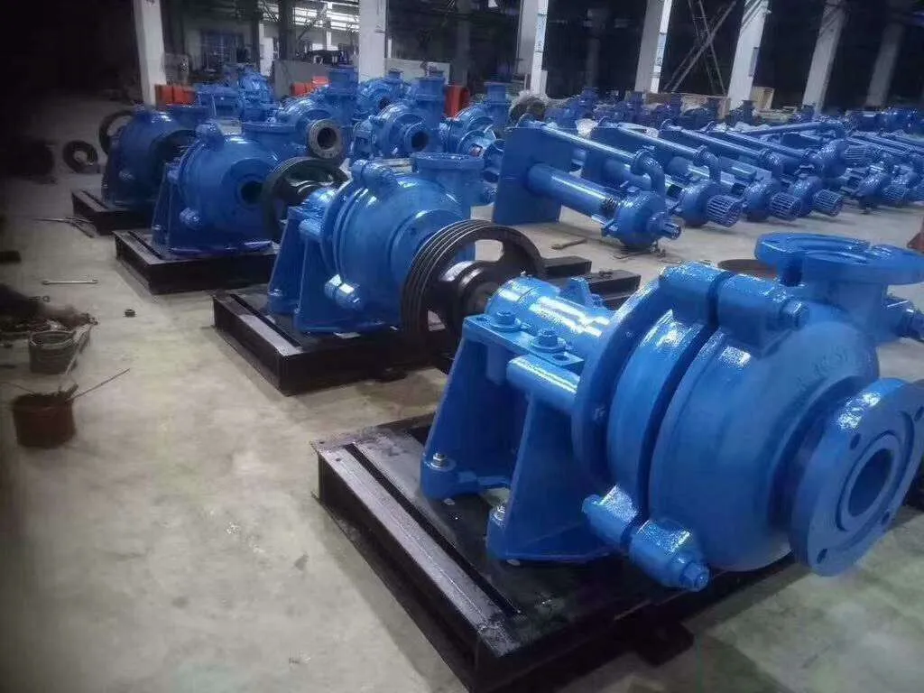
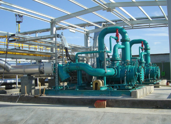
Lime slurry pumping is a critical process in numerous industrial applications, including flue gas desulfurization (FGD) in power plants, wastewater treatment, mineral processing, and soil stabilization. It involves the transportation of a heterogeneous mixture of hydrated lime (calcium hydroxide, Ca(OH)₂) and water, often containing solids loading up to 70% by weight. This process presents unique challenges due to the abrasive nature of the lime particles, the tendency for settling and stratification within the slurry, and the potential for scale buildup within the pumping system. The technical position within the broader industrial chain places lime slurry pumping as a pivotal element in environmental control, resource recovery, and process optimization. Core performance is characterized by volumetric flow rate, pressure head, slurry concentration handling capability, and long-term reliability against abrasive wear and corrosion. Selecting the appropriate pumping technology and implementing proper operational procedures are essential for efficient and cost-effective lime slurry handling. Failure to do so results in increased maintenance costs, process downtime, and potential environmental non-compliance.
Material Science & Manufacturing
The primary raw material, hydrated lime, is produced through the hydration of quicklime (calcium oxide, CaO). The quality of the hydrated lime significantly impacts pump performance. Particle size distribution, ranging from coarse to fine, affects slurry viscosity and abrasivity. Finer particles increase viscosity but reduce settling; coarser particles are more abrasive. Water quality also plays a role; impurities can affect slurry chemistry and promote scaling. Pump components are typically manufactured from high-chrome cast iron, stainless steel (304, 316), or specialized polymers (UHMWPE, polyurethane) to resist abrasion and corrosion. Manufacturing processes vary depending on pump type. Centrifugal pumps utilize precision casting and machining for impellers and casings. Positive displacement pumps (e.g., progressing cavity pumps) involve complex rotor-stator assembly. Welding procedures for steel components require careful control of heat input and filler metal composition to maintain material properties and prevent weld defects. Rubber linings, applied through vulcanization, provide corrosion resistance, but their adhesion and durability are critical. Key parameter control includes monitoring slurry pH, temperature, and solids concentration during manufacturing to ensure compatibility with pump materials. The crystalline structure of the chrome carbide within the cast iron is crucial, with a higher volume fraction of carbides leading to improved wear resistance. Proper heat treatment is essential to optimize this structure.
Performance & Engineering
Performance of lime slurry pumps is governed by several engineering principles. Hydraulic design must account for the non-Newtonian behavior of the slurry, particularly at high solids concentrations. Force analysis considers the impact forces from abrasive particles on pump components, leading to wear. The pump’s net positive suction head required (NPSHr) is critical to prevent cavitation, exacerbated by the slurry’s density. Environmental resistance is paramount, particularly in FGD applications where exposure to sulfur dioxide, chlorides, and other corrosive compounds is common. Compliance requirements, such as those outlined by the EPA for FGD systems, dictate material selection and pump performance parameters. Functional implementation involves proper piping design to minimize head loss and avoid localized velocity spikes. Pump speed control allows for optimization of flow rate and pressure based on process demands. Finite element analysis (FEA) is used to model stress distribution within pump components under abrasive wear conditions. Computational fluid dynamics (CFD) simulates slurry flow patterns, identifying areas prone to erosion or sedimentation. The selection of impeller geometry (radial, axial, or mixed flow) is influenced by the desired head and flow characteristics. Pump curves detailing head-capacity relationships are crucial for system design and operation. Dynamic sealing systems, such as mechanical seals, must withstand abrasive slurry and maintain leak-free operation.
Technical Specifications
| Parameter | Centrifugal Pump (High Chrome) | Progressing Cavity Pump (UHMWPE Stator) | Diaphragm Pump (Rubber Lined) | Vertical Turbine Pump (SS316) |
|---|---|---|---|---|
| Maximum Solids Concentration (%) | 65 | 80 | 70 | 50 |
| Flow Rate (m³/hr) | 0-200 | 0-50 | 0-100 | 0-300 |
| Discharge Pressure (bar) | 0-15 | 0-20 | 0-10 | 0-30 |
| Abrasive Wear Rate (mm/year) | 0.1-0.5 | 0.05-0.2 | 0.2-0.8 | 0.08-0.3 |
| Pump Efficiency (%) | 60-75 | 50-65 | 40-55 | 70-85 |
| Slurry pH Range | 8-12 | 6-13 | 5-14 | 7-13 |
Failure Mode & Maintenance
Lime slurry pumps are susceptible to several failure modes. Abrasive wear is the most common, leading to impeller erosion, liner degradation, and increased clearances. Corrosion, especially in FGD applications, causes pitting and material loss. Cavitation, resulting from inadequate NPSH, damages impeller surfaces. Scale buildup, due to lime precipitation, reduces pump efficiency and can cause blockages. Mechanical seal failures are frequent, caused by abrasive particles and chemical attack. Fatigue cracking can occur in pump casings and impellers under cyclic loading. Delamination of rubber linings compromises corrosion resistance. Oxidation of metallic components degrades material properties. Maintenance solutions include regular inspection of pump components for wear and corrosion. Preventive replacement of wear parts (liners, impellers, seals) based on operating hours and slurry characteristics. Periodic cleaning to remove scale buildup. Proper lubrication of bearings and seals. Slurry pre-treatment to remove large particles or adjust pH. Implementation of a vibration monitoring program to detect early signs of mechanical problems. Root cause analysis of failures to identify and address underlying issues. Use of high-quality spare parts and adherence to manufacturer’s recommendations are vital for long-term reliability. Monitoring slurry temperature and viscosity is also important.
Industry FAQ
Q: What is the primary cause of impeller wear in centrifugal lime slurry pumps?
A: The primary cause of impeller wear is the abrasive nature of the lime particles in the slurry. The high-velocity impact of these particles erodes the impeller material, particularly at the leading edges and outlet vanes. The severity of wear is directly related to the particle size distribution, solids concentration, and slurry velocity.
Q: How does the choice of elastomer affect the performance of a progressing cavity pump handling lime slurry?
A: The elastomer (e.g., UHMWPE, EPDM) of the stator significantly influences the pump’s performance. UHMWPE offers excellent abrasion resistance but lower chemical resistance. EPDM provides better chemical resistance but is more susceptible to abrasion. Selecting the appropriate elastomer depends on the slurry’s chemical composition and solids concentration. Hardness and elongation properties of the elastomer also play a role.
Q: What are the key considerations for selecting a mechanical seal for a lime slurry pump?
A: Key considerations include the seal material, seal face configuration, and flushing system. Silicone carbide or tungsten carbide seal faces are preferred for their abrasion resistance. A robust flushing system, using clean water or a compatible slurry, is crucial to prevent abrasive particles from lodging between the seal faces. Double mechanical seals with a barrier fluid provide enhanced reliability.
Q: What preventative measures can be taken to mitigate scale buildup in lime slurry pipelines and pumps?
A: Preventative measures include maintaining proper slurry pH, controlling slurry temperature, and minimizing stagnant zones in the piping system. Chemical additives, such as polyphosphates, can be used to inhibit scale formation. Regular pigging of pipelines removes accumulated scale. Proper pump sizing and operation to avoid low flow velocities can also help prevent scale buildup.
Q: What is the significance of NPSHr and NPSHa in lime slurry pumping applications?
A: NPSHr (Net Positive Suction Head Required) is the minimum pressure required at the pump suction to prevent cavitation. NPSHa (Net Positive Suction Head Available) is the actual pressure available at the pump suction. NPSHa must always be greater than NPSHr to ensure stable pump operation. Cavitation damages impeller surfaces and reduces pump efficiency. Careful system design and pump selection are crucial to ensure adequate NPSHa.
Conclusion
Lime slurry pumping represents a complex engineering challenge requiring careful consideration of material science, hydraulic design, and operational parameters. The selection of the appropriate pump technology – centrifugal, progressing cavity, diaphragm, or vertical turbine – is dictated by the specific application requirements, including slurry concentration, flow rate, pressure, and chemical composition. Proactive maintenance strategies, including regular inspection, preventative replacement of wear parts, and root cause analysis of failures, are essential for ensuring long-term reliability and minimizing downtime.
Future advancements in lime slurry pumping technology will likely focus on the development of more abrasion-resistant materials, improved impeller designs to enhance hydraulic efficiency, and advanced monitoring systems to predict and prevent failures. The integration of artificial intelligence (AI) and machine learning (ML) for predictive maintenance and process optimization offers significant potential. Continued research into slurry rheology and the development of new chemical additives to inhibit scale formation will also contribute to improved performance and reduced operating costs.
-
Comprehensive Guide to Waterproof ORings for Optimal Sealing Solutions
News2026-06-09
-
Septic Pump Replacement Performance Analysis
News2026-06-10
-
Septic Pump Price Performance Analysis
News2026-06-10
-
pumps for septic systems Material Science Manufacturing
News2026-06-10
-
ejector pumps for basement bathrooms Performance Analysis
News2026-06-10
-
Ejector Pump Cost Analysis
News2026-06-10
-
drainage pumps Performance and Engineering
News2026-06-09
-
basement bathroom ejector pump Material Science
News2026-06-09
-
Sewer Ejector Pump Cost Performance Analysis
News2026-06-09
-
Septic Tank Pump Replacement Performance Analysis
News2026-06-09
-
septic sump pump Performance and Engineering
News2026-06-09
-
Septic Pump System Performance Analysis
News2026-06-08
-
pump for septic Material Science
News2026-06-08
-
basement sewer pump Performance Analysis
News2026-06-08
-
submerged pump Performance Engineering
News2026-06-08


