English
- Afrikaans
- Albanian
- Amharic
- Arabic
- Armenian
- Azerbaijani
- Basque
- Belarusian
- Bengali
- Bosnian
- Bulgarian
- Catalan
- Cebuano
- Corsican
- Croatian
- Czech
- Danish
- Dutch
- English
- Esperanto
- Estonian
- Finnish
- French
- Frisian
- Galician
- Georgian
- German
- Greek
- Gujarati
- Haitian Creole
- hausa
- hawaiian
- Hebrew
- Hindi
- Miao
- Hungarian
- Icelandic
- igbo
- Indonesian
- irish
- Italian
- Japanese
- Javanese
- Kannada
- kazakh
- Khmer
- Rwandese
- Korean
- Kurdish
- Kyrgyz
- Lao
- Latin
- Latvian
- Lithuanian
- Luxembourgish
- Macedonian
- Malgashi
- Malay
- Malayalam
- Maltese
- Maori
- Marathi
- Mongolian
- Myanmar
- Nepali
- Norwegian
- Norwegian
- Occitan
- Pashto
- Persian
- Polish
- Portuguese
- Punjabi
- Romanian
- Russian
- Samoan
- Scottish Gaelic
- Serbian
- Sesotho
- Shona
- Sindhi
- Sinhala
- Slovak
- Slovenian
- Somali
- Spanish
- Sundanese
- Swahili
- Swedish
- Tagalog
- Tajik
- Tamil
- Tatar
- Telugu
- Thai
- Turkish
- Turkmen
- Ukrainian
- Urdu
- Uighur
- Uzbek
- Vietnamese
- Welsh
- Bantu
- Yiddish
- Yoruba
- Zulu
 Co., Ltd.")
Telephone: +86 13120555503
Email: frank@cypump.com


Apr . 01, 2024 17:55 Back to list
homemade slurry pump Manufacturing Specification and Performance Analysis
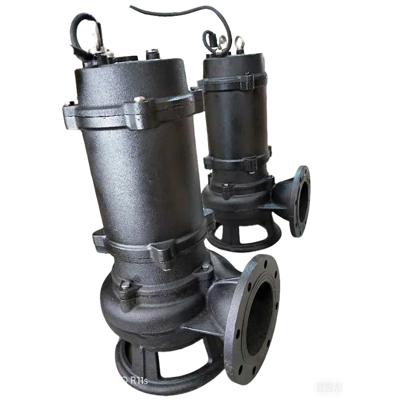
Homemade Slurry Pump Manufacturing Specification and Performance Analysis
A homemade slurry pump, in an industrial context, refers to a custom-engineered centrifugal or positive displacement pump designed specifically for the transport of non-Newtonian fluids containing suspended solid particles. Unlike standard water pumps, slurry pumps must address the critical challenges of abrasive wear, corrosive chemical interactions, and high fluid viscosity. Positioned at the intersection of mining, wastewater treatment, and chemical processing, these systems serve as the primary conduit for tailings, ore slurries, and industrial sludge. The technical core of such a system lies in its ability to maintain a critical carrying velocity—preventing the sedimentation of solids—while minimizing the erosion of internal wetted parts. This guide provides a comprehensive engineering analysis of the materials, fluid dynamics, and structural integrity required to manufacture a high-performance slurry handling system.
Material Science & Manufacturing
The manufacturing of a slurry pump begins with the selection of materials capable of resisting hydro-abrasive wear. The primary failure mechanism in slurry transport is "three-body abrasion," where particles are trapped between the fluid and the pump wall. To combat this, high-chromium cast irons (ASTM A532) are typically employed for impellers and liners, utilizing a matrix of hard M7C3 carbides to provide a hardness typically exceeding 60 HRC. For more corrosive environments, duplex stainless steels or high-nickel alloys are selected to prevent pitting and stress corrosion cracking.
The manufacturing process involves several critical stages:
1. Casting and Heat Treatment: The impeller is cast using precision molds to ensure hydraulic balance. Post-casting, a rigorous quenching and tempering cycle is implemented to refine the grain structure and optimize the distribution of carbides.
2. Precision Machining: The volute casing is machined to ensure concentricity between the shaft and the housing, reducing turbulence and localized erosion zones.
3. Dynamic Balancing: To prevent premature bearing failure and vibration-induced fatigue, the impeller undergoes G2.5 grade dynamic balancing.
4. Surface Hardening: Critical wear areas may undergo laser cladding or tungsten carbide coating to increase the surface hardness of the wear plates, effectively extending the Mean Time Between Failures (MTBF).
Performance & Engineering
Engineering a slurry pump requires a deep understanding of fluid mechanics, specifically the transition from laminar to turbulent flow in multi-phase fluids. The primary design objective is the optimization of the Critical Settling Velocity (Vc). If the flow velocity drops below this threshold, solids precipitate, leading to pipeline blockage and catastrophic pump failure. Engineers utilize the Durand equation to calculate the required velocity based on particle diameter, density, and fluid viscosity.
Force analysis is centered on the NPSHr (Net Positive Suction Head Required). Slurries, due to their higher density and viscosity, exhibit significantly higher friction losses in the suction line. To avoid cavitation—which causes rapid pitting of the impeller vanes—the pump is designed with an enlarged suction eye and a low-velocity inlet. Furthermore, the seal engineering is critical; a combination of a mechanical seal and a gland packing system with a pressurized flushing line is utilized to prevent abrasive particles from entering the bearing housing, thereby ensuring the structural integrity of the rotating assembly under high-pressure conditions.
Technical Specifications
| Performance Metric | Low-Density Slurry | Medium-Density Slurry | High-Density Slurry | Unit of Measurement |
|---|---|---|---|---|
| Maximum Flow Rate | 150 | 100 | 60 | m³/h |
| Total Dynamic Head | 45 | 35 | 20 | Meters |
| Maximum Solid Concentration | 15% | 30% | 55% | Weight % |
| Impeller Hardness | 55-60 | 60-65 | 65-72 | HRC |
| Operational Speed | 1450 | 1200 | 900 | RPM |
| Efficiency Rating | 78% | 72% | 61% | Percentage |
Failure Mode & Maintenance
The failure modes of slurry pumps are predominantly driven by the aggressive nature of the pumped medium. The most common failure is Abrasive Wear, which manifests as the thinning of the impeller vanes and the erosion of the volute liner. This leads to a gradual increase in the gap between the impeller and the casing, causing a drop in discharge pressure and overall efficiency. Another critical failure mode is Cavitation Erosion, occurring when vapor bubbles collapse against the metal surface, creating micro-jets that carve out the material.
Maintenance protocols must be rigorous and preventative:
1. Vibration Analysis: Monthly monitoring of the bearing housings using accelerometers to detect misalignment or impeller imbalance.
2. Wear Measurement: Utilizing ultrasonic thickness gauges to monitor the remaining wall thickness of the volute liner without dismantling the pump.
3. Lubrication Management: Implementing a high-viscosity synthetic lubricant with anti-wear additives to maintain the hydrodynamic film in the bearings.
4. Seal Replacement: Systematic replacement of packing rings and mechanical seal faces based on leakage rates, ensuring that no slurry penetrates the shaft assembly.
Industry FAQ
Q: How do we determine the optimal impeller material for a high-silica slurry?
A: For high-silica applications, where the abrasive index is extreme, we recommend high-chromium white irons (ASTM A532 Class III) or ceramic-lined components. The high volume fraction of chromium carbides provides the necessary hardness to resist the cutting action of silica particles.
Q: What is the impact of slurry viscosity on the pump's NPSHr?
A: Increased viscosity increases the friction loss in the suction piping and requires more energy to accelerate the fluid into the impeller eye. This elevates the NPSHr, meaning the pump requires a higher suction pressure to avoid cavitation compared to pumping clear water.
Q: Why is the pump experiencing premature seal failure despite using high-grade materials?
A: This is often due to "particle bridging" in the seal gap. If the flushing water pressure is lower than the pump internal pressure, slurry enters the seal face. Ensuring a positive pressure differential (typically 1-2 bar higher than the stuffing box pressure) is essential.
Q: Can a homemade slurry pump handle fluids with a pH below 4.0?
A: Standard high-chrome irons are susceptible to acid attack. For pH levels below 4.0, the wetted parts must be upgraded to duplex stainless steels (e.g., CD4MCu) or specialized polymer liners to prevent chemical corrosion from undermining the abrasive resistance.
Q: How does the solids-to-liquid ratio affect the pump's power consumption?
A: As the concentration of solids increases, the apparent density and viscosity of the slurry rise, significantly increasing the brake horsepower (BHP) required. The motor must be sized with a safety margin of at least 20% to accommodate fluctuations in slurry density.
Conclusion
The engineering of a homemade slurry pump is a complex exercise in balancing hydraulic efficiency with material durability. By integrating high-chromium alloys, optimizing the critical settling velocity, and implementing a rigorous NPSH analysis, it is possible to construct a system that withstands the extreme conditions of industrial slurry transport. The success of the pump depends not only on the initial material selection but on the precision of the manufacturing tolerances and the adherence to dynamic balancing standards.
Looking forward, the integration of smart sensors for real-time wear monitoring and the adoption of additive manufacturing for complex impeller geometries promise to further enhance the lifespan and efficiency of slurry handling systems. For operators, the transition from reactive to predictive maintenance—driven by vibration and thickness data—remains the most effective strategy for reducing operational downtime and maximizing the lifecycle of these critical industrial assets.
-
Comprehensive Guide to Waterproof ORings for Optimal Sealing Solutions
News2026-06-09
-
Septic Pump System Performance Analysis
News2026-06-08
-
pump for septic Material Science
News2026-06-08
-
basement sewer pump Performance Analysis
News2026-06-08
-
submerged pump Performance Engineering
News2026-06-08
-
Septic System Pumps Performance Analysis
News2026-06-08
-
septic system pump Material Science and Manufacturing
News2026-06-07
-
pump for septic tank Material Science Manufacturing
News2026-06-07
-
submersible sewage pump Material Science
News2026-06-07
-
Sewage Ejector Material Science and Manufacturing
News2026-06-07
-
Ejection Pump Material Science
News2026-06-07
-
pump submersible Performance Analysis
News2026-06-06
-
ejector pumps Performance Engineering
News2026-06-06
-
basement ejector pump Material Science Manufacturing
News2026-06-06
-
Septic Tanks Pumping Performance Analysis
News2026-06-06


