English
- Afrikaans
- Albanian
- Amharic
- Arabic
- Armenian
- Azerbaijani
- Basque
- Belarusian
- Bengali
- Bosnian
- Bulgarian
- Catalan
- Cebuano
- Corsican
- Croatian
- Czech
- Danish
- Dutch
- English
- Esperanto
- Estonian
- Finnish
- French
- Frisian
- Galician
- Georgian
- German
- Greek
- Gujarati
- Haitian Creole
- hausa
- hawaiian
- Hebrew
- Hindi
- Miao
- Hungarian
- Icelandic
- igbo
- Indonesian
- irish
- Italian
- Japanese
- Javanese
- Kannada
- kazakh
- Khmer
- Rwandese
- Korean
- Kurdish
- Kyrgyz
- Lao
- Latin
- Latvian
- Lithuanian
- Luxembourgish
- Macedonian
- Malgashi
- Malay
- Malayalam
- Maltese
- Maori
- Marathi
- Mongolian
- Myanmar
- Nepali
- Norwegian
- Norwegian
- Occitan
- Pashto
- Persian
- Polish
- Portuguese
- Punjabi
- Romanian
- Russian
- Samoan
- Scottish Gaelic
- Serbian
- Sesotho
- Shona
- Sindhi
- Sinhala
- Slovak
- Slovenian
- Somali
- Spanish
- Sundanese
- Swahili
- Swedish
- Tagalog
- Tajik
- Tamil
- Tatar
- Telugu
- Thai
- Turkish
- Turkmen
- Ukrainian
- Urdu
- Uighur
- Uzbek
- Vietnamese
- Welsh
- Bantu
- Yiddish
- Yoruba
- Zulu
 Co., Ltd.")
Telephone: +86 13120555503
Email: frank@cypump.com


Apr . 01, 2024 17:55 Back to list
froth slurry pump Performance Analysis and Manufacturing Specifications
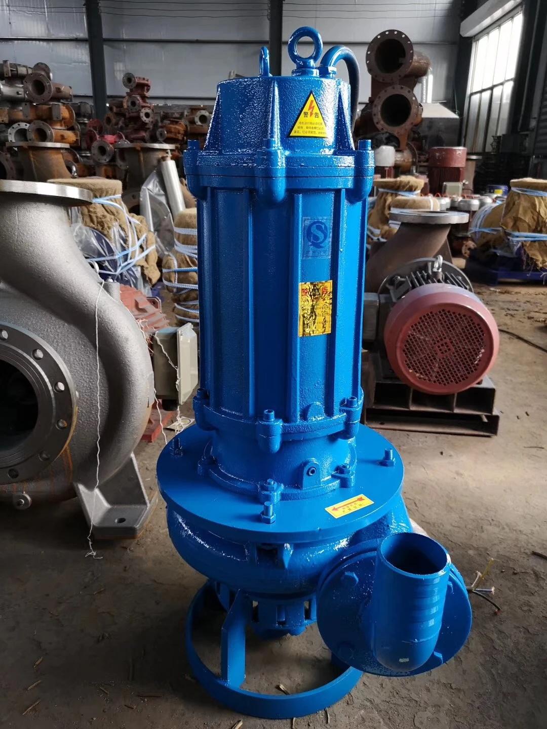
Froth Slurry Pump Performance Analysis and Manufacturing Specifications
The froth slurry pump is a specialized centrifugal pumping system engineered for the transport of high-density mineral slurries containing significant volumes of air or froth, typically encountered in the flotation cells of mineral processing plants. Unlike conventional slurry pumps, froth slurry pumps must address the critical challenge of "air binding" and the resulting loss of prime, which can lead to catastrophic cavitation and premature impeller failure. Positioned as a critical asset in the metallurgical value chain, these pumps bridge the gap between the flotation process and the thickening or filtration stages. Their core performance is defined by the ability to maintain a steady volumetric flow rate despite fluctuating solids concentrations and high gas-to-liquid ratios, ensuring that the metallurgical recovery rate is not compromised by hydraulic instability.
Material Science & Manufacturing
The manufacturing of froth slurry pumps requires an advanced understanding of tribology and material fatigue. The primary failure mechanism in these systems is a combination of abrasive wear (from mineral particles) and corrosive attack (from chemical reagents used in flotation). To mitigate this, the wetted parts—specifically the impeller and volute liner—are typically manufactured from high-chrome white irons (ASTM A532) or specialized elastomer linings. High-chrome alloys (typically 27% Cr) provide a hard martensitic matrix with embedded M7C3 carbides, offering superior resistance to sliding abrasion.
The manufacturing process involves precision investment casting followed by rigorous heat treatment to ensure a uniform hardness profile across the component cross-section. For the shaft, duplex stainless steel is often employed to prevent stress corrosion cracking (SCC) and pitting. A critical manufacturing specification is the dynamic balancing of the impeller to ISO 1940-1 standards, which minimizes vibration-induced wear on the mechanical seals and bearings. Furthermore, the pump casing is often designed with a "froth-handling" geometry, utilizing a wider suction eye and specific vane profiles to prevent the accumulation of air pockets, which would otherwise cause the pump to lose prime and operate in a dry-run condition.
Performance & Engineering
Engineering a froth slurry pump necessitates a complex force analysis to manage the interaction between the liquid phase, solid particles, and entrained air. The primary engineering challenge is the management of the Net Positive Suction Head (NPSHr). In froth applications, the presence of air increases the effective volume of the fluid, which can lead to a sudden drop in pressure at the impeller eye, triggering cavitation. To counteract this, engineers implement "air-handling" modifications, such as specialized vortex breakers in the sump and optimized impeller discharge angles to ensure efficient gas expulsion.
Environmental resistance is another pillar of the engineering design. The pump must withstand fluctuating pH levels resulting from flotation modifiers (such as xanthates or cyanides). Consequently, the sealing system is usually a dual-pressurized mechanical seal or an expeller seal (face seal) that utilizes a diverted flow of the slurry itself to cool and lubricate the sealing faces. From a compliance perspective, the pump must adhere to strict energy efficiency standards and noise emission limits. The hydraulic design is optimized using Computational Fluid Dynamics (CFD) to minimize internal turbulence, which not only reduces power consumption but also prevents the shearing of fragile mineral flocs, preserving the integrity of the froth mineral concentration.
Technical Specifications
| Parameter Dimension | High-Chrome Alloy Spec | Natural Rubber Lined Spec | Duplex Steel Spec | Performance Metric |
|---|---|---|---|---|
| Hardness (Brinell/Shore) | 600 - 650 HB | 65 - 75 Shore A | 250 - 300 HB | Wear Resistance |
| Max Particle Size (mm) | Up to 12 mm | Up to 8 mm | Up to 10 mm | Throughput Capacity |
| Max Slurry Density (g/cm³) | 1.8 - 2.2 | 1.4 - 1.7 | 1.6 - 2.0 | Volumetric Efficiency |
| Operating Temp Range (°C) | -20 to 150 | -10 to 70 | -40 to 200 | Thermal Stability |
| Corrosion Rate (mm/year) | 0.1 - 0.3 | Negligible | 0.05 - 0.15 | Chemical Compatibility |
| MTBF (Operating Hours) | 8,000 - 12,000 | 5,000 - 7,000 | 15,000 - 20,000 | Service Reliability |
Failure Mode & Maintenance
Failure analysis of froth slurry pumps typically reveals three primary modes: abrasive erosion, cavitation-induced pitting, and mechanical seal degradation. Abrasive erosion occurs most frequently at the impeller vanes and the volute tongue, where fluid velocities are highest. This is characterized by a "scalloping" effect on the metal surface. Cavitation occurs when air pockets collapse violently against the impeller surfaces, creating micro-jets that remove material at a molecular level, leading to a porous, "sponge-like" appearance of the metal.
Maintenance protocols must be predictive rather than reactive. We recommend the implementation of vibration monitoring (accelerometers) to detect early signs of bearing wear or impeller imbalance. Regular ultrasonic thickness testing of the volute liner is mandatory to prevent catastrophic "burn-through" of the casing. For the sealing system, a strict flush-water pressure regime must be maintained; if the flush water pressure drops below the internal pump pressure, slurry will ingress into the seal chamber, causing immediate face failure. Maintenance schedules should include the quarterly inspection of the wear plate clearances to ensure that the pump's efficiency does not drop below the critical 65% threshold.
Industry FAQ
Q: How does the presence of froth specifically impact the NPSH requirements of the pump?
A: Froth introduces a compressible gas phase into the liquid, which significantly lowers the effective vapor pressure of the mixture. This increases the Net Positive Suction Head Required (NPSHr). If the available NPSH falls below this threshold, the pump will experience air binding, leading to a loss of hydraulic lift and potential overheating of the mechanical seals.
Q: When should we prioritize High-Chrome alloys over Elastomer linings for the pump internals?
A: High-Chrome alloys are preferred when the slurry contains large, sharp-edged particles or operates at higher temperatures where elastomers would degrade. Elastomer linings are superior for fine-particle slurries with high impact energy, as the rubber absorbs the kinetic energy of the particle rather than resisting it through hardness.
Q: What is the primary cause of premature impeller failure in froth applications?
A: The primary cause is "unbalanced erosion." Because froth is not homogeneous, one side of the impeller may experience higher abrasive loads than the other. This creates a dynamic imbalance, leading to shaft deflection, which accelerates the wear of the bearings and the mechanical seal faces.
Q: How can we prevent the pump from losing prime during high-froth surges?
A: The most effective engineering solution is the installation of a specialized froth-handling suction manifold or a recessed impeller design that minimizes the formation of air vortices. Additionally, implementing a variable frequency drive (VFD) allows the operator to adjust the pump speed to match the froth density and maintain a constant flow.
Q: Which international standards govern the testing and acceptance of these pumps?
A: The design and testing usually follow ISO 5199 for centrifugal pumps and HI (Hydraulic Institute) standards for performance testing. Material specifications are typically governed by ASTM A532 for high-chrome irons and ASTM A240 for stainless steel components.
Conclusion
The operational efficiency of a froth slurry pump is inextricably linked to the synergy between its material composition and its hydraulic architecture. By utilizing high-chrome alloys and precision-engineered air-handling geometries, these pumps can withstand the extreme abrasive and corrosive environments typical of mineral flotation. The technical density of the system—from the metallurgical structure of the impeller to the precision of the mechanical seals—determines the overall uptime and throughput of the mineral processing plant.
Looking forward, the integration of IoT-based condition monitoring and CFD-optimized impeller geometries will further reduce the total cost of ownership. Industry stakeholders should focus on transitioning from scheduled maintenance to predictive maintenance models, ensuring that wear components are replaced based on actual degradation data rather than arbitrary time intervals, thereby maximizing the reliability of the metallurgical recovery process.
-
Comprehensive Guide to Waterproof ORings for Optimal Sealing Solutions
News2026-06-09
-
Septic Pump System Performance Analysis
News2026-06-08
-
pump for septic Material Science
News2026-06-08
-
basement sewer pump Performance Analysis
News2026-06-08
-
submerged pump Performance Engineering
News2026-06-08
-
Septic System Pumps Performance Analysis
News2026-06-08
-
septic system pump Material Science and Manufacturing
News2026-06-07
-
pump for septic tank Material Science Manufacturing
News2026-06-07
-
submersible sewage pump Material Science
News2026-06-07
-
Sewage Ejector Material Science and Manufacturing
News2026-06-07
-
Ejection Pump Material Science
News2026-06-07
-
pump submersible Performance Analysis
News2026-06-06
-
ejector pumps Performance Engineering
News2026-06-06
-
basement ejector pump Material Science Manufacturing
News2026-06-06
-
Septic Tanks Pumping Performance Analysis
News2026-06-06


