English
- Afrikaans
- Albanian
- Amharic
- Arabic
- Armenian
- Azerbaijani
- Basque
- Belarusian
- Bengali
- Bosnian
- Bulgarian
- Catalan
- Cebuano
- Corsican
- Croatian
- Czech
- Danish
- Dutch
- English
- Esperanto
- Estonian
- Finnish
- French
- Frisian
- Galician
- Georgian
- German
- Greek
- Gujarati
- Haitian Creole
- hausa
- hawaiian
- Hebrew
- Hindi
- Miao
- Hungarian
- Icelandic
- igbo
- Indonesian
- irish
- Italian
- Japanese
- Javanese
- Kannada
- kazakh
- Khmer
- Rwandese
- Korean
- Kurdish
- Kyrgyz
- Lao
- Latin
- Latvian
- Lithuanian
- Luxembourgish
- Macedonian
- Malgashi
- Malay
- Malayalam
- Maltese
- Maori
- Marathi
- Mongolian
- Myanmar
- Nepali
- Norwegian
- Norwegian
- Occitan
- Pashto
- Persian
- Polish
- Portuguese
- Punjabi
- Romanian
- Russian
- Samoan
- Scottish Gaelic
- Serbian
- Sesotho
- Shona
- Sindhi
- Sinhala
- Slovak
- Slovenian
- Somali
- Spanish
- Sundanese
- Swahili
- Swedish
- Tagalog
- Tajik
- Tamil
- Tatar
- Telugu
- Thai
- Turkish
- Turkmen
- Ukrainian
- Urdu
- Uighur
- Uzbek
- Vietnamese
- Welsh
- Bantu
- Yiddish
- Yoruba
- Zulu
 Co., Ltd.")
Telephone: +86 13120555503
Email: frank@cypump.com


Apr . 01, 2024 17:55 Back to list
concrete slurry pump Performance Analysis and Manufacturing Specifications
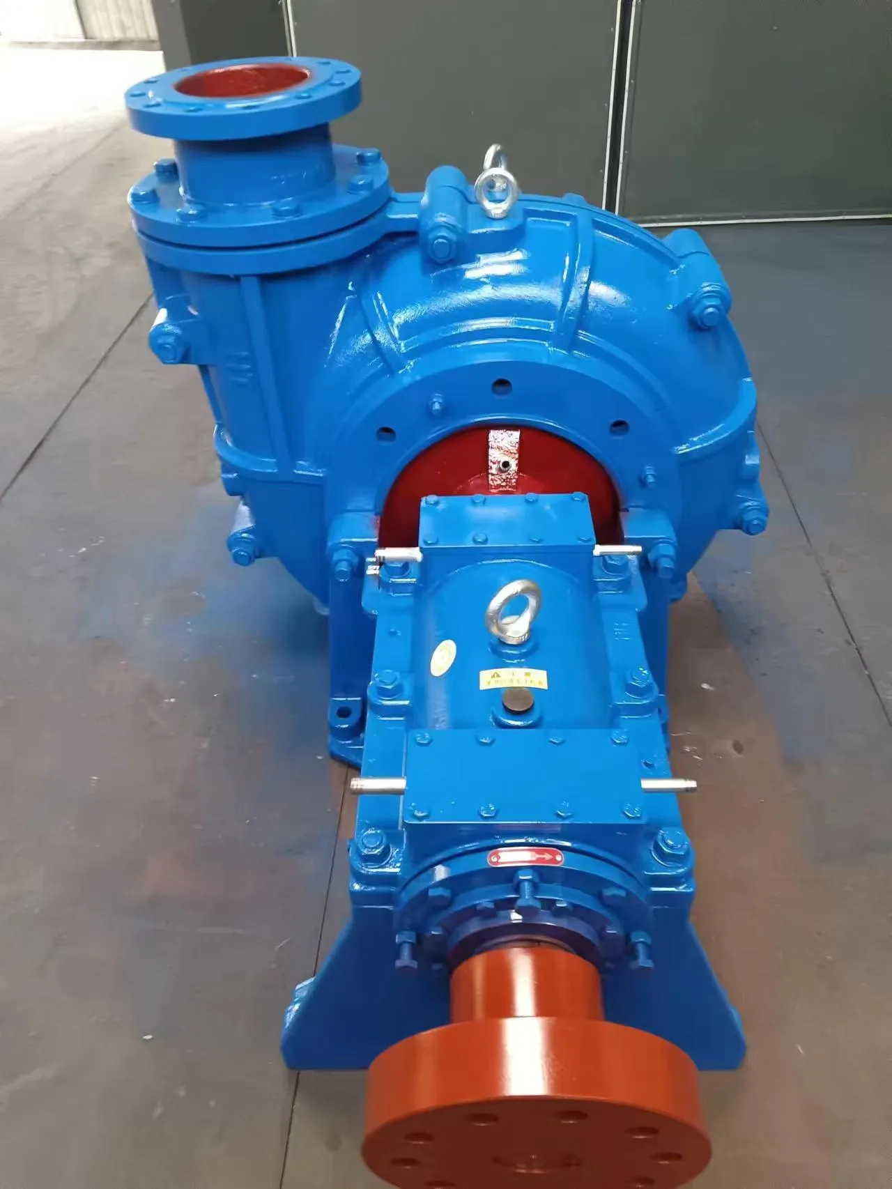
Concrete Slurry Pump Performance Analysis and Manufacturing Specifications
The concrete slurry pump is a specialized positive displacement machine engineered to transport highly viscous, abrasive, and non-Newtonian fluids—specifically cementitious slurries, grouting materials, and concrete—over significant distances and elevations. Within the industrial construction chain, the slurry pump serves as the critical link between the batching plant and the final casting site. Unlike standard centrifugal pumps, concrete slurry pumps are designed to overcome the extreme shear resistance and high yield stress characteristic of cement-based mixtures. The technical core of these machines lies in their ability to maintain a constant flow rate despite fluctuating head pressures, ensuring a homogenous distribution of materials without phase separation. Performance is primarily governed by the pump's volumetric efficiency, its ability to handle high aggregate concentrations, and its resistance to the severe erosive wear caused by the quartz and calcite particles inherent in concrete aggregates.
Material Science & Manufacturing
The manufacturing of concrete slurry pumps necessitates an advanced understanding of tribology and metallurgy, as the equipment is subjected to simultaneous abrasive wear and corrosive attack from the alkaline nature of cement. The primary structural components, specifically the cylinder liners and delivery pipes, are typically fabricated from high-chromium cast iron (ASTM A532) or hardened alloy steels. These materials are selected for their martensitic structure, which provides a hardness typically exceeding 60 HRC, essential for resisting the scouring action of coarse aggregates.
The manufacturing process involves precision casting followed by a controlled heat treatment cycle—including quenching and tempering—to eliminate internal stresses and ensure uniform hardness across the component's geometry. For the piston-driven systems, the seals are engineered using a combination of polyurethane and reinforced synthetic rubbers, which offer a high modulus of elasticity and superior resistance to the tearing forces exerted by the slurry. The pumping cylinders are often honed to a mirror finish (Ra < 0.4 μm) to minimize friction and prolong the lifespan of the sealing elements.
In the assembly phase, the integration of the hydraulic system is paramount. The use of high-pressure hydraulic cylinders and proportional valves allows for the precise control of the piston stroke and speed. Manufacturing tolerances for the pump's internal clearances are kept within microns to prevent "slip" or backflow, which would otherwise significantly reduce the volumetric efficiency and lead to localized turbulence and accelerated wear within the valve seats.

Performance & Engineering
Engineering a concrete slurry pump requires a rigorous force analysis of the fluid dynamics involving Bingham plastics. The flow of concrete slurry does not follow a linear relationship between pressure and flow rate; instead, it requires a minimum "yield stress" to be overcome before movement begins. The pump's engineering focuses on the "pressure-to-flow" ratio, ensuring that the maximum discharge pressure can overcome the frictional resistance of the pipeline, which increases linearly with the length of the pipe and the viscosity of the mix.
A critical engineering challenge is the prevention of "plugging" or blockages. This is addressed through the implementation of S-valves or ring-valves that ensure a seamless transition of the slurry from the hopper to the delivery cylinder. The hydraulic circuit is designed with integrated pressure relief valves to protect the structural integrity of the pump in the event of a line blockage, preventing catastrophic failure of the cylinder walls or pipeline ruptures.
Environmental resistance is also a key engineering priority. Because these pumps operate in harsh construction environments, the exterior chassis is treated with high-build epoxy coatings to prevent oxidation. Furthermore, the cooling systems for the hydraulic oil are oversized to ensure that the pump can operate continuously in ambient temperatures exceeding 45°C without the degradation of hydraulic fluid viscosity, which would otherwise lead to sluggish response times and overheating of the seals.
Technical Specifications
| Parameter Dimension | Standard Series (Medium) | Heavy Duty Series (High) | Ultra-High Pressure Series | Evaluation Metric |
|---|---|---|---|---|
| Maximum Discharge Pressure | 8.5 MPa | 12.0 MPa | 18.0 MPa | Pascal (Pa) |
| Theoretical Flow Rate | 30-60 m³/h | 60-100 m³/h | 100-150 m³/h | Cubic Meters / Hour |
| Max Aggregate Size | 20 mm | 40 mm | 40 mm | Millimeters (mm) |
| Cylinder Diameter | 230 mm | 230 mm | 250 mm | Millimeters (mm) |
| Piston Stroke Length | 1200 mm | 1500 mm | 1800 mm | Millimeters (mm) |
| Motor Power / Torque | 15 kW / 400 Nm | 22 kW / 600 Nm | 30 kW / 800 Nm | kW / Newton-meters |
Failure Mode & Maintenance
The primary failure mode in concrete slurry pumps is abrasive wear, specifically localized in the valve seats and cylinder liners. This manifests as "grooving," where the hard aggregates carve channels into the metal surface, leading to internal leakage and a drop in discharge pressure. Another frequent failure is "seal blowout," caused by the ingress of coarse aggregates between the piston and the cylinder wall, which lacerates the polyurethane seals. Fatigue cracking in the pump frame may also occur if the machine is subjected to repeated pressure spikes beyond its design limit.
Professional maintenance requires a predictive approach centered on wear-measurement protocols. Liners should be measured using internal calipers every 500 operating hours; once the inner diameter exceeds the nominal specification by 5%, replacement is mandatory to maintain volumetric efficiency. For seal maintenance, a strict lubrication schedule using alkaline-resistant lubricants is essential to reduce the friction coefficient.
To prevent oxidation and chemical degradation, all hydraulic components must be flushed and the oil analyzed for water contamination (Karl Fischer titration) every quarter. If the slurry is particularly aggressive (e.g., containing accelerators), the delivery pipes should be inspected for wall-thinning using ultrasonic thickness gauges to prevent burst failures during high-pressure operations.
Industry FAQ
Q: How do we determine the correct pump pressure for a specific vertical lift?
A: The required pressure is calculated by summing the static head (height × slurry density) and the frictional head loss (which depends on pipe diameter, slurry viscosity, and flow velocity). We typically add a 20% safety margin to account for the initial "break-out" pressure required to move the stationary slurry column.
Q: What causes sudden pressure spikes during the pumping cycle?
A: Pressure spikes are usually caused by "slugging," where an inconsistent mix with high aggregate concentration enters the cylinder, or by air pockets in the suction line. Ensuring a consistent water-to-cement ratio and utilizing a properly primed hopper can mitigate these fluctuations.
Q: Why is the pump experiencing premature wear in the delivery valve?
A: This is often the result of "segregation," where the heavier aggregates settle at the bottom of the pipe and create a concentrated abrasive stream. Increasing the flow velocity to maintain a turbulent flow regime helps keep the aggregates in suspension and distributes the wear more evenly.
Q: Can these pumps handle high-slump concrete without modification?
A: Yes, however, high-slump concrete increases the risk of "slip" through the seals. For very fluid mixes, we recommend adjusting the seal tension or utilizing a different polyurethane compound with a higher hardness rating to prevent leakage.
Q: What is the impact of ambient temperature on hydraulic efficiency?
A: Low temperatures increase hydraulic oil viscosity, slowing the piston cycle and increasing energy consumption. High temperatures decrease viscosity, potentially leading to internal leakage in the valves. We utilize thermostatic valves to maintain the oil within an optimal 40°C to 60°C range.
Conclusion
The concrete slurry pump is a sophisticated piece of industrial machinery where material science and fluid dynamics intersect. Its operational success depends on the synergy between high-chromium alloy metallurgy and precision hydraulic control. By addressing the fundamental challenges of abrasive wear and non-Newtonian flow, these pumps enable the construction of complex infrastructure that would be impossible with traditional pouring methods.
Looking forward, the integration of smart sensors for real-time wear monitoring and the adoption of variable-frequency drives (VFD) will further optimize energy efficiency and reduce downtime. For procurement and engineering teams, the focus must remain on total cost of ownership (TCO), prioritizing the quality of wear parts and the robustness of the hydraulic system over initial acquisition cost to ensure long-term operational stability.
-
Comprehensive Guide to Waterproof ORings for Optimal Sealing Solutions
News2026-06-09
-
Septic Pump System Performance Analysis
News2026-06-08
-
pump for septic Material Science
News2026-06-08
-
basement sewer pump Performance Analysis
News2026-06-08
-
submerged pump Performance Engineering
News2026-06-08
-
Septic System Pumps Performance Analysis
News2026-06-08
-
septic system pump Material Science and Manufacturing
News2026-06-07
-
pump for septic tank Material Science Manufacturing
News2026-06-07
-
submersible sewage pump Material Science
News2026-06-07
-
Sewage Ejector Material Science and Manufacturing
News2026-06-07
-
Ejection Pump Material Science
News2026-06-07
-
pump submersible Performance Analysis
News2026-06-06
-
ejector pumps Performance Engineering
News2026-06-06
-
basement ejector pump Material Science Manufacturing
News2026-06-06
-
Septic Tanks Pumping Performance Analysis
News2026-06-06


