English
- Afrikaans
- Albanian
- Amharic
- Arabic
- Armenian
- Azerbaijani
- Basque
- Belarusian
- Bengali
- Bosnian
- Bulgarian
- Catalan
- Cebuano
- Corsican
- Croatian
- Czech
- Danish
- Dutch
- English
- Esperanto
- Estonian
- Finnish
- French
- Frisian
- Galician
- Georgian
- German
- Greek
- Gujarati
- Haitian Creole
- hausa
- hawaiian
- Hebrew
- Hindi
- Miao
- Hungarian
- Icelandic
- igbo
- Indonesian
- irish
- Italian
- Japanese
- Javanese
- Kannada
- kazakh
- Khmer
- Rwandese
- Korean
- Kurdish
- Kyrgyz
- Lao
- Latin
- Latvian
- Lithuanian
- Luxembourgish
- Macedonian
- Malgashi
- Malay
- Malayalam
- Maltese
- Maori
- Marathi
- Mongolian
- Myanmar
- Nepali
- Norwegian
- Norwegian
- Occitan
- Pashto
- Persian
- Polish
- Portuguese
- Punjabi
- Romanian
- Russian
- Samoan
- Scottish Gaelic
- Serbian
- Sesotho
- Shona
- Sindhi
- Sinhala
- Slovak
- Slovenian
- Somali
- Spanish
- Sundanese
- Swahili
- Swedish
- Tagalog
- Tajik
- Tamil
- Tatar
- Telugu
- Thai
- Turkish
- Turkmen
- Ukrainian
- Urdu
- Uighur
- Uzbek
- Vietnamese
- Welsh
- Bantu
- Yiddish
- Yoruba
- Zulu
 Co., Ltd.")
Telephone: +86 13120555503
Email: frank@cypump.com


Apr . 01, 2024 17:55 Back to list
Centrifugal Slurry Pumps slurry transport using centrifugal pumps Technical Analysis and Hydraulic P
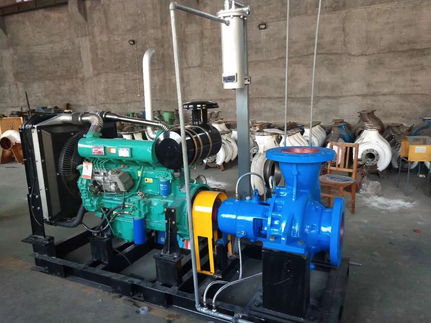
Centrifugal Slurry Pumps: Technical Analysis and Hydraulic Performance
Slurry transport using centrifugal pumps is a critical industrial process involving the movement of non-Newtonian fluids consisting of solid particles suspended in a liquid carrier. In the industrial chain, these pumps act as the primary kinetic energy source to overcome frictional losses and hydrostatic head, ensuring the continuous flow of tailings, ore pulps, and chemical slurries. The technical challenge lies in managing the dual nature of the medium: the fluid dynamics of the carrier liquid and the abrasive mechanical impact of the suspended solids. Effective slurry transport requires a precise equilibrium between the critical carrying velocity—the minimum speed necessary to prevent particle sedimentation—and the pump's operational efficiency to mitigate excessive wear. This guide examines the intersection of material science, fluid mechanics, and mechanical engineering required to maintain system integrity in high-abrasion environments.
Material Science & Manufacturing
The manufacturing of centrifugal slurry pumps focuses on combating three primary degradation mechanisms: abrasive wear, corrosive attack, and erosive cavitation. The selection of materials for the impeller and volute casing is governed by the hardness and chemical composition of the transported solids.
High-Chromium White Irons (ASTM A532): For high-abrasion applications, alloys containing 25% to 28% chromium are utilized. These materials form hard M7C3 carbides within a martensitic matrix, providing a hardness typically exceeding 60 HRC. The manufacturing process involves precise heat treatment—specifically quenching and tempering—to ensure the carbides are finely distributed, preventing localized pitting.
Natural and Synthetic Elastomers: In applications involving fine, sharp particles, rubber-lined components are preferred. Natural rubber (NR) is employed for its superior resilience and ability to absorb the kinetic energy of impacting particles, effectively "bouncing" them off the surface. Polyurethane is utilized where higher tear strength and oil resistance are required. The bonding process involves vulcanization of the rubber lining to a steel substrate, requiring strict temperature and pressure control to prevent delamination.
Manufacturing Precision: The casting of volutes requires rigorous shrinkage control to maintain hydraulic profiles. Impellers are often dynamically balanced to G2.5 standards to reduce vibration-induced fatigue. The internal surfaces are precision-ground or polished to reduce boundary layer turbulence, which otherwise accelerates localized erosion (eddy current wear) near the impeller eye and discharge throat.

Performance & Engineering
Engineering a slurry transport system necessitates a deep understanding of the slurry's rheology. Unlike clean water, slurries exhibit varying viscosity based on the solids concentration (Cw) and particle size distribution (PSD). The primary engineering objective is to maintain the flow velocity above the "deposition velocity" to prevent pipeline blockage, while keeping it below the "critical erosion velocity" to prolong component life.
Hydraulic Force Analysis: The pump must compensate for the increased density of the slurry, which directly impacts the Brake Horsepower (BHP). The power requirement is calculated by incorporating the specific gravity (SG) of the mixture: $BHP = (Q imes H imes SG) / (367 imes eta)$, where $eta$ represents the pump efficiency, which is significantly lower in slurry service than in water service due to internal friction and solids slip.
Net Positive Suction Head (NPSH) Considerations: Slurries are prone to cavitation, particularly if air is entrained or if the solids concentrate at the suction eye. Engineering specifications must ensure that the NPSH available (NPSHa) exceeds the NPSH required (NPSHr) by a safety margin of at least 1.5 to 2.0. This is achieved through the use of larger suction piping and reducing the vertical lift from the sump to the pump centerline.
Seal Engineering: To prevent the ingress of abrasive particles into the bearing housing, heavy-duty expeller seals or mechanical seals with external flushing (API Plan 32 or 54) are implemented. The expeller seal creates a centrifugal barrier that forces the slurry away from the shaft, eliminating the need for packing glands that would otherwise wear out rapidly.
Technical Specifications
| Material Grade | Hardness (HRC/Shore A) | Max Particle Size (mm) | Typical Application | Wear Resistance Index | Corrosion Resistance |
|---|---|---|---|---|---|
| High-Chrome (27% Cr) | 62-68 HRC | Up to 12mm | Mine Tailings/Coarse Ore | Ultra-High | Moderate |
| Natural Rubber | 65-75 Shore A | Up to 3mm | Fine Sand/Acid Slurry | High (Impact) | Excellent |
| Duplex Stainless Steel | 25-35 HRC | Up to 2mm | Chemical Process Slurry | Moderate | Ultra-High |
| Polyurethane | 90-95 Shore A | Up to 5mm | Waste Water Grits | High (Abrasion) | Good |
| Hardened Cast Iron | 45-55 HRC | Up to 6mm | Low-Concentration Slurry | Moderate | Low |
| Ceramic Composite | >80 HRC | Up to 1mm | High-Precision Polishing | Extreme | Excellent |
Failure Mode & Maintenance
Failure in centrifugal slurry pumps is rarely sudden; it is typically the result of cumulative degradation. The most prevalent failure modes include:
Abrasive Erosion: This occurs when high-velocity particles impact the impeller vanes and volute liners. The "thinning" of these components leads to a drop in discharge pressure and a shift in the pump's performance curve. Failure is identified through vibration analysis and periodic ultrasonic thickness testing of the casing.
Cavitation Pitting: Vapor bubbles collapsing against the impeller surface create micro-jets that strip away the protective oxide layer of the metal. This is often mistaken for erosion but is characterized by a "sponge-like" surface texture. Solution: Increase suction head or reduce pump speed via Variable Frequency Drive (VFD).
Mechanical Seal Failure: Slurry leakage into the bearing housing leads to rapid bearing seizure. This is caused by the abrasive particles breaching the seal faces. Maintenance requires the implementation of a strict lubrication schedule and the use of high-viscosity synthetic lubricants to repel fine particulates.
Maintenance Protocol: A predictive maintenance strategy is mandatory. This includes: 1. Monthly vibration spectral analysis to detect impeller imbalance. 2. Quarterly clearance checks between the impeller and the wear plate to ensure volumetric efficiency. 3. Immediate replacement of liners once they reach 50% of their original thickness to prevent catastrophic casing breach.
Industry FAQ
Q: How do we determine the critical carrying velocity to avoid pipeline sedimentation?
A: The critical velocity is determined by the Durand equation, which considers the particle diameter, the density difference between the solid and the liquid, and the pipe diameter. For most mineral slurries, the velocity must be maintained 0.3 to 0.6 m/s above the deposition velocity to ensure a homogeneous suspension.
Q: Why is the pump efficiency significantly lower when transporting slurry compared to water?
A: This is due to "solids slip" and increased apparent viscosity. The solid particles do not move at the same velocity as the liquid carrier, creating internal shear layers that dissipate energy. Additionally, the higher density increases the frictional drag against the pipe walls and pump internals.
Q: When should we choose a rubber-lined pump over a high-chrome alloy pump?
A: Rubber lining is superior for fine particles (typically < 2mm) and high-impact environments where the particles are sharp but small. High-chrome alloys are required for coarse, large particles that would tear or puncture a rubber liner through mechanical gouging.
Q: What is the impact of slurry concentration on the NPSH required?
A: Increasing the solids concentration (Cw) increases the viscosity and the density of the fluid, which generally increases the NPSH required. This makes the pump more susceptible to cavitation, necessitating a higher suction head or a lower rotational speed.
Q: How does a VFD improve the lifecycle of a slurry pump?
A: Wear rates in slurry pumps are proportional to the cube of the velocity ($Wear propto V^3$). By using a VFD to operate the pump at the minimum required velocity for transport rather than throttling a valve, the wear rate is exponentially reduced, significantly extending the mean time between failures (MTBF).
Conclusion
The engineering of slurry transport using centrifugal pumps is a sophisticated balance of hydraulic optimization and material endurance. By integrating high-chromium alloys and advanced elastomers with a rigorous understanding of non-Newtonian fluid dynamics, operators can mitigate the inherent risks of abrasive wear and cavitation. The technical success of the system depends not only on the initial pump selection but on the continuous monitoring of critical carrying velocities and the strict adherence to predictive maintenance schedules.
Looking forward, the industry is shifting toward "smart pumping" systems, where real-time sensors for slurry density and vibration are integrated with AI-driven VFDs. This evolution will allow for dynamic adjustment of flow rates based on real-time rheological changes, further optimizing energy consumption and extending the operational lifespan of critical components in the most demanding industrial environments.
-
sump pump for septic systems Material Science Manufacturing
News2026-05-20
-
sump pump and ejector pump Material Science Manufacturing
News2026-05-20
-
sewage treatment plant pumps Performance Analysis
News2026-05-20
-
sewage tank pump Material Science and Manufacturing
News2026-05-20
-
sewage pump for septic tank Performance Analysis
News2026-05-20
-
Sewage Pump and Tank Performance Analysis
News2026-05-19
-
Sewage Ejector Pump Replacement Performance Analysis
News2026-05-19
-
sewage ejector pump for basement bathroom Material Science Manufacturing
News2026-05-19
-
sewage ejection pump Material Science and Manufacturing
News2026-05-19
-
in line sewage pump Performance Analysis
News2026-05-19
-
effluent sump pump Performance Analysis
News2026-05-18
-
best grinder pump for sewage Performance Engineering
News2026-05-18
-
basement waste water pump Performance Engineering
News2026-05-18
-
sump pump sewer Performance Analysis
News2026-05-18
-
sump pump for sewer Performance Analysis
News2026-05-18


