English
- Afrikaans
- Albanian
- Amharic
- Arabic
- Armenian
- Azerbaijani
- Basque
- Belarusian
- Bengali
- Bosnian
- Bulgarian
- Catalan
- Cebuano
- Corsican
- Croatian
- Czech
- Danish
- Dutch
- English
- Esperanto
- Estonian
- Finnish
- French
- Frisian
- Galician
- Georgian
- German
- Greek
- Gujarati
- Haitian Creole
- hausa
- hawaiian
- Hebrew
- Hindi
- Miao
- Hungarian
- Icelandic
- igbo
- Indonesian
- irish
- Italian
- Japanese
- Javanese
- Kannada
- kazakh
- Khmer
- Rwandese
- Korean
- Kurdish
- Kyrgyz
- Lao
- Latin
- Latvian
- Lithuanian
- Luxembourgish
- Macedonian
- Malgashi
- Malay
- Malayalam
- Maltese
- Maori
- Marathi
- Mongolian
- Myanmar
- Nepali
- Norwegian
- Norwegian
- Occitan
- Pashto
- Persian
- Polish
- Portuguese
- Punjabi
- Romanian
- Russian
- Samoan
- Scottish Gaelic
- Serbian
- Sesotho
- Shona
- Sindhi
- Sinhala
- Slovak
- Slovenian
- Somali
- Spanish
- Sundanese
- Swahili
- Swedish
- Tagalog
- Tajik
- Tamil
- Tatar
- Telugu
- Thai
- Turkish
- Turkmen
- Ukrainian
- Urdu
- Uighur
- Uzbek
- Vietnamese
- Welsh
- Bantu
- Yiddish
- Yoruba
- Zulu

Telephone: +86 13120555503
Email: frank@cypump.com


Apr . 01, 2024 17:55 Back to list
centrifugal slurry pumps Performance Analysis and Manufacturing Specifications
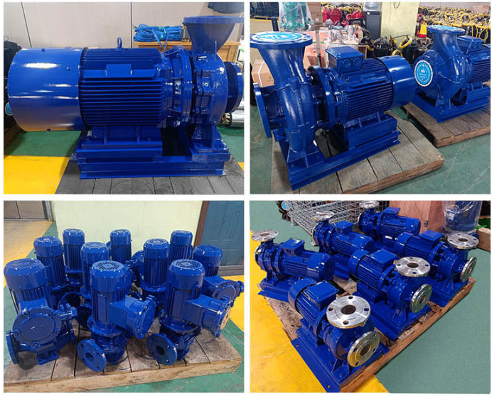
Centrifugal Slurry Pumps Performance Analysis and Manufacturing Specifications
Introduction
Centrifugal slurry pumps are specialized heavy-duty rotating machines engineered to transport abrasive solids suspended in liquids, commonly referred to as slurries. Unlike standard water pumps, these machines are positioned at the critical intersection of fluid dynamics and tribology within the industrial chain, serving as the primary motive force in mining, mineral processing, dredging, and chemical power plant ash handling. The core technical objective of a centrifugal slurry pump is to maintain a stable flow rate and head while mitigating the extreme erosive and corrosive effects caused by the high kinetic energy of particulate matter. Their performance is governed by the complex interplay between the impeller geometry, the slurry's volumetric concentration, and the metallurgy of the wetted parts, ensuring that the system can handle varying densities without succumbing to premature catastrophic failure.
Material Science & Manufacturing
The longevity of a centrifugal slurry pump is fundamentally determined by the material science applied to its internal components. Given the aggressive nature of slurries, manufacturers employ advanced metallurgy to balance hardness and toughness. High-chromium cast irons (typically 27% Cr) are the industry standard for high-abrasion environments, utilizing a eutectic structure of hard primary carbides (M7C3) embedded in a martensitic matrix to resist scouring. For applications involving high acidity or salinity, duplex stainless steels or chemically bonded rubber linings are utilized to prevent electrochemical corrosion.
The manufacturing process involves precision casting and rigorous thermal treatment. The impeller and volute are typically produced via sand casting, followed by a strict heat-treatment cycle to optimize the hardness profile. Critical to the manufacturing stage is the "dynamic balancing" of the impeller to minimize radial vibrations, which would otherwise accelerate seal failure. Furthermore, the precision machining of the wear plate and the impeller clearance is vital; an excessive gap leads to internal recirculation and efficiency loss, while an overly tight gap can cause seizing if the slurry contains oversized particulates. The application of rubber lining involves high-pressure vulcanization to ensure a seamless bond between the elastomer and the steel shell, eliminating the risk of delamination under vacuum or high-pressure conditions.
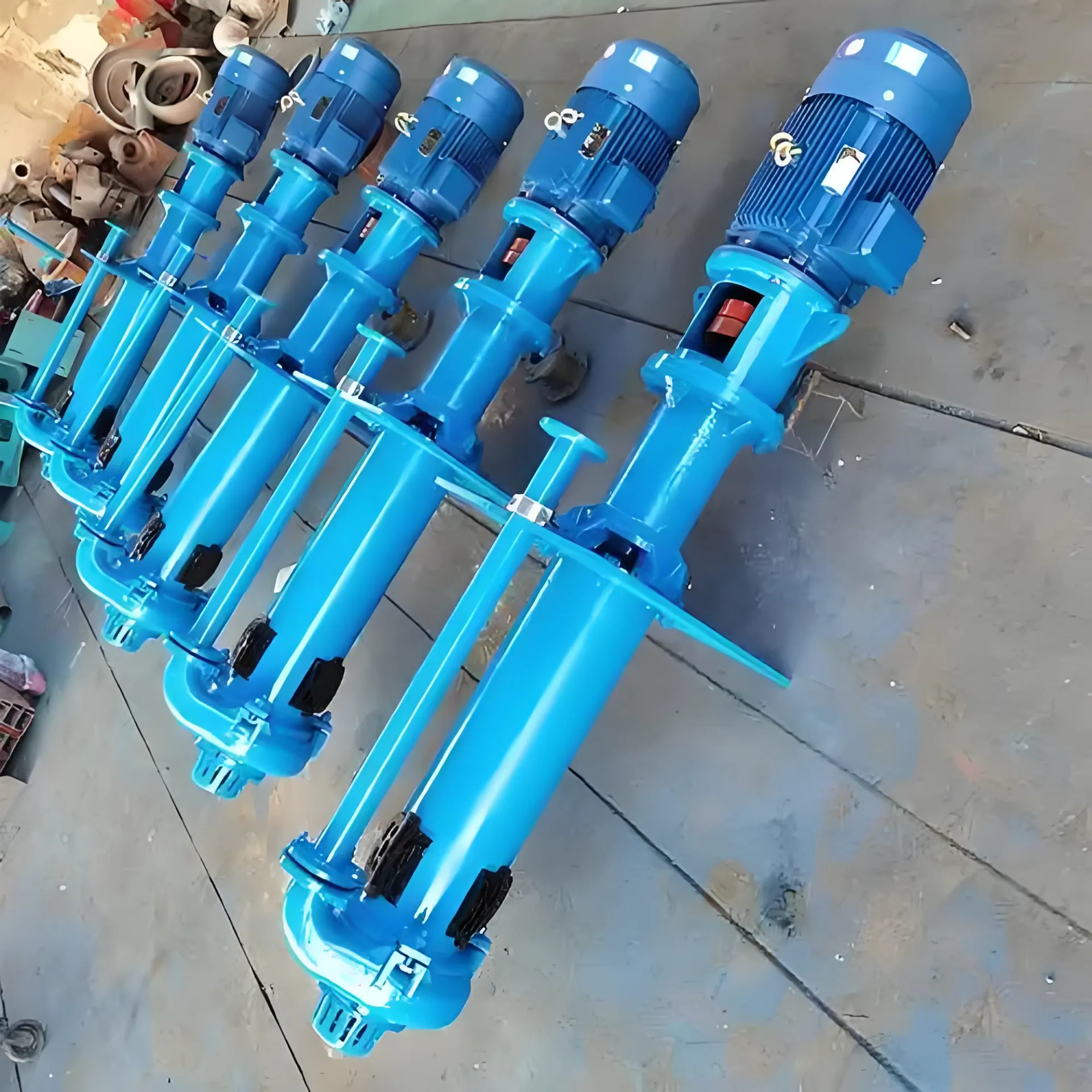
Performance & Engineering
Engineering a centrifugal slurry pump requires a deep analysis of the fluid's rheology. The primary challenge is the "derating" of the pump; as the slurry density increases, the required power increases and the head produced decreases compared to clean water. This is calculated using the slurry correction factor, which accounts for the increased viscosity and the presence of solids. Force analysis focuses on the hydraulic thrust acting on the shaft, which is managed through a robust bearing housing and heavy-duty shafting to prevent deflection.
Environmental resistance is managed through specialized sealing systems. The expeller (or booster) seal is a critical engineering feature that creates a centrifugal barrier, pushing the slurry away from the stuffing box to prevent leakage and reduce the wear on the gland packing or mechanical seal. Furthermore, the velocity of the slurry within the pump must be maintained above the "critical settling velocity" to prevent solids from depositing in the volute, which would cause clogging and uneven wear (localized erosion). Compliance with engineering standards ensures that the pump can operate under varying Net Positive Suction Head (NPSH) conditions to avoid cavitation, which can lead to rapid pitting of the impeller vanes.
Technical Specifications
| Technical Parameter | High-Chrome Alloy Series | Natural Rubber Lined Series | Duplex Stainless Series | Unit of Measure |
|---|---|---|---|---|
| Maximum Particle Size | 12.0 | 8.0 | 6.0 | mm |
| Max Operating Pressure | 2.5 | 1.2 | 2.0 | MPa |
| Hardness (Rockwell C) | 60-65 | N/A (Shore A 60) | 30-35 | HRC |
| Corrosion Resistance | Moderate | Excellent (Acidic) | Superior (Chloride) | Rating |
| Max Flow Rate | 1200 | 800 | 1000 | m³/h |
| Max Discharge Head | 110 | 60 | 90 | m |
Failure Mode & Maintenance
Failure analysis of centrifugal slurry pumps reveals three primary modes of degradation: erosive wear, corrosive pitting, and mechanical fatigue. Erosive wear occurs predominantly at the impeller vane tips and the volute tongue, where the fluid velocity is highest. This results in a loss of hydraulic efficiency and an increase in NPSHr. Corrosive failure often manifests as "pitting," where the protective oxide layer of the metal is breached, leading to localized deep cavities. Mechanical failure, specifically shaft fatigue cracking, is often a byproduct of misalignment or operating the pump too far from its Best Efficiency Point (BEP), causing excessive radial loads.
Professional maintenance protocols mandate the use of vibration analysis to detect bearing wear before failure occurs. To combat erosion, a "sacrificial wear liner" strategy is employed, where replaceable liners are installed in the volute to protect the main casing. Maintenance schedules should include the regular inspection of the impeller clearance; when the gap exceeds the manufacturer's specification, the impeller must be replaced or rebuilt. For rubber-lined pumps, checking for "blistering" or delamination is critical, as slurry penetrating the liner can rapidly corrode the outer steel shell, leading to a sudden casing breach.
Industry FAQ
Q: How do we determine whether to use high-chrome alloy or rubber lining for a specific slurry?
A: The decision depends on the particle size and hardness. High-chrome alloys are superior for large, sharp, and hard particles that would cut through rubber. Rubber lining is preferred for fine particles and highly corrosive chemical slurries where abrasion is secondary to chemical attack.
Q: What is the impact of slurry density on the pump's total dynamic head (TDH)?
A: Increased slurry density increases the fluid's viscosity and internal friction, which leads to a reduction in the TDH and flow rate compared to water. This necessitates the use of correction factors during the pump selection process to avoid under-sizing the motor.
Q: Why does the pump experience severe vibration when operating at low flow rates?
A: Operating far to the left of the BEP increases the radial force on the impeller, causing shaft deflection and instability. This not only causes vibration but also accelerates the wear of the mechanical seals and bearings.
Q: How can we prevent cavitation in high-density slurry applications?
A: To prevent cavitation, ensure the NPSHa (Available) is significantly higher than the NPSHr (Required). This can be achieved by increasing the suction head, reducing the slurry temperature, or using a larger suction pipe diameter to minimize friction losses.
Q: What is the primary cause of premature failure in the expeller seal?
A: The most common cause is the accumulation of solids in the seal chamber due to improper flushing or a worn expeller vane, which allows the slurry to bypass the centrifugal barrier and attack the primary sealing elements.
Conclusion
The engineering of centrifugal slurry pumps is a complex balance between material hardness, hydraulic efficiency, and mechanical robustness. By integrating high-chromium metallurgy and precision manufacturing, these pumps are capable of handling the most aggressive industrial fluids, provided that they are operated within their specified hydraulic envelopes. The transition from standard water pumping to slurry transport requires a fundamental shift in focus toward wear-rate prediction and the management of solids-induced turbulence.
Looking forward, the industry is moving toward "intelligent monitoring," utilizing IoT sensors for real-time wear tracking and predictive maintenance. Optimizing the impeller geometry through Computational Fluid Dynamics (CFD) will continue to reduce energy consumption and extend the mean time between failures (MTBF). For procurement and engineering teams, the emphasis must remain on the total cost of ownership, prioritizing material compatibility and engineering precision over initial acquisition costs.
-
sewage effluent pumps Material Science Manufacturing
News2026-05-27
-
septic tank effluent pump Performance Analysis
News2026-05-27
-
Septic Sewer Pump Performance Analysis
News2026-05-27
-
septic sewage pumps Performance Analysis
News2026-05-27
-
septic sewage pump Material Science and Manufacturing
News2026-05-27
-
residential sewage pumps Material Science and Manufacturing
News2026-05-26
-
residential sewage lift pump Performance Analysis
News2026-05-26
-
high head sump pump Performance and Engineering
News2026-05-26
-
effluent pump for septic tank Material Science Manufacturing
News2026-05-26
-
effluent and sewage pumps Material Science Manufacturing
News2026-05-26
-
1 2 hp sewage ejector pump Performance Engineering
News2026-05-25
-
Zoeller 1/2 hp sewage pump Performance Analysis
News2026-05-25
-
Effluent Pump Performance Analysis
News2026-05-25
-
sump pump vs effluent pump Performance Analysis
News2026-05-25
-
sewer pumps residential Performance Analysis
News2026-05-25