English
- Afrikaans
- Albanian
- Amharic
- Arabic
- Armenian
- Azerbaijani
- Basque
- Belarusian
- Bengali
- Bosnian
- Bulgarian
- Catalan
- Cebuano
- Corsican
- Croatian
- Czech
- Danish
- Dutch
- English
- Esperanto
- Estonian
- Finnish
- French
- Frisian
- Galician
- Georgian
- German
- Greek
- Gujarati
- Haitian Creole
- hausa
- hawaiian
- Hebrew
- Hindi
- Miao
- Hungarian
- Icelandic
- igbo
- Indonesian
- irish
- Italian
- Japanese
- Javanese
- Kannada
- kazakh
- Khmer
- Rwandese
- Korean
- Kurdish
- Kyrgyz
- Lao
- Latin
- Latvian
- Lithuanian
- Luxembourgish
- Macedonian
- Malgashi
- Malay
- Malayalam
- Maltese
- Maori
- Marathi
- Mongolian
- Myanmar
- Nepali
- Norwegian
- Norwegian
- Occitan
- Pashto
- Persian
- Polish
- Portuguese
- Punjabi
- Romanian
- Russian
- Samoan
- Scottish Gaelic
- Serbian
- Sesotho
- Shona
- Sindhi
- Sinhala
- Slovak
- Slovenian
- Somali
- Spanish
- Sundanese
- Swahili
- Swedish
- Tagalog
- Tajik
- Tamil
- Tatar
- Telugu
- Thai
- Turkish
- Turkmen
- Ukrainian
- Urdu
- Uighur
- Uzbek
- Vietnamese
- Welsh
- Bantu
- Yiddish
- Yoruba
- Zulu

Telephone: +86 13120555503
Email: frank@cypump.com


Apr . 01, 2024 17:55 Back to list
cement slurry grouting pump Technical Analysis and Manufacturing Specifications
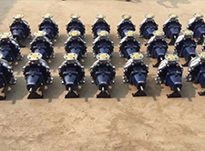
Cement Slurry Grouting Pump: Technical Analysis and Manufacturing Specifications
The cement slurry grouting pump is a high-precision industrial displacement machine engineered to transport non-Newtonian, highly abrasive, and visco-elastic cementitious suspensions into subterranean voids, rock fractures, or structural interfaces. In the industrial chain, it occupies a critical position between the mixing plant and the injection point, serving as the primary mechanism for pressure control and volumetric accuracy in soil stabilization, dam curtain grouting, and tunnel reinforcement. The core performance of these pumps is defined by their ability to maintain a constant flow rate under fluctuating back-pressures, ensuring the homogeneous distribution of the grout to prevent "piping" or incomplete filling, which could compromise the structural integrity of the entire civil engineering project.
Material Science & Manufacturing
The manufacturing of cement slurry grouting pumps necessitates a rigorous selection of materials capable of resisting extreme erosive wear and chemical corrosion induced by the alkaline nature of cement (pH typically between 12 and 13). The fluid end, specifically the cylinders and pistons, is typically constructed from high-chromium cast iron or forged carbon steel with a hard-chrome plated interior. This minimizes the coefficient of friction and increases the surface hardness to resist the scouring action of cement particles (typically 10-100 microns).
From a manufacturing perspective, the precision of the piston-to-cylinder clearance is the primary control parameter. If the clearance is too wide, internal leakage (slip) occurs, reducing volumetric efficiency; if too tight, the abrasive slurry can cause rapid galling and seizure. Advanced pumps utilize a "double-seal" configuration involving a primary high-pressure polyurethane seal and a secondary graphite-reinforced PTFE seal to prevent slurry leakage into the hydraulic drive system. The chassis is typically fabricated using heavy-duty welded structural steel, subjected to stress-relieving heat treatment to prevent deformation under high-pressure cyclic loading. The drive system employs high-torque hydraulic motors with variable displacement pumps, allowing for the precise modulation of the injection rate, which is critical to avoid hydro-fracturing the surrounding geological strata.
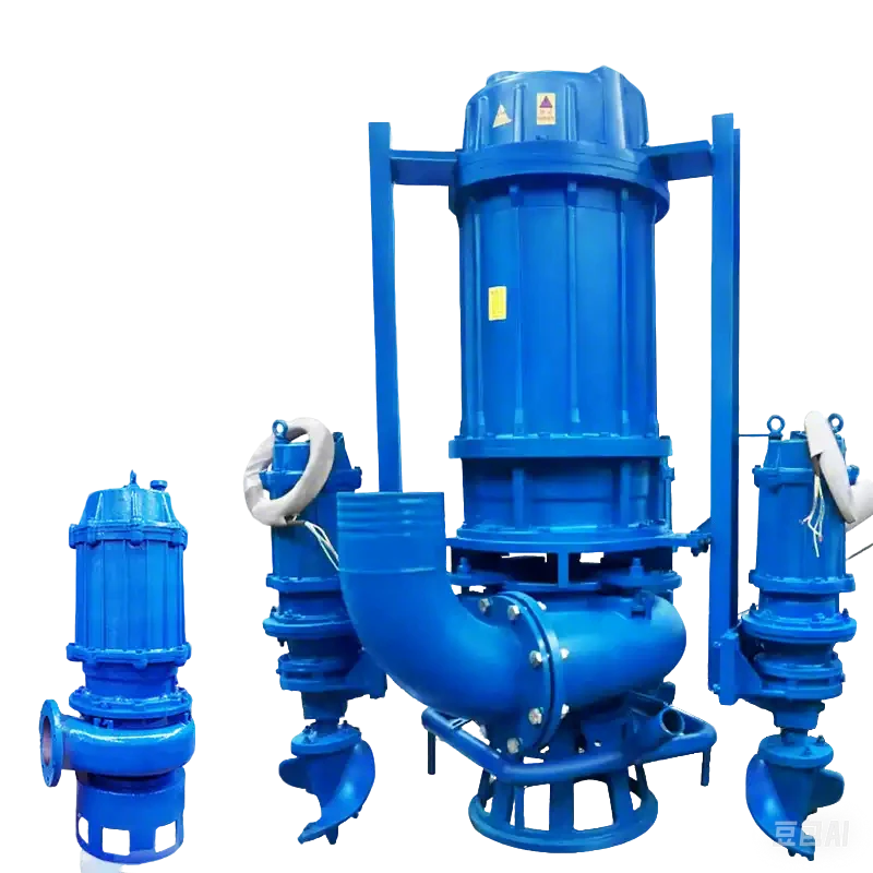
Performance & Engineering
The engineering efficiency of a grouting pump is analyzed through the lens of fluid dynamics and force distribution. Cement slurry behaves as a Bingham plastic, meaning it requires a minimum yield stress to begin flowing. The pump must provide sufficient initial pressure (breakout pressure) to overcome this yield stress, followed by a steady-state pressure to maintain flow. Engineering calculations focus on the Pressure Drop ($Delta P$), which is a function of the slurry viscosity, the pipeline diameter, and the distance of transport. To minimize friction losses, the internal geometry of the pump valves and manifolds is optimized using Computational Fluid Dynamics (CFD) to reduce turbulence and stagnant zones where cement could prematurely hydrate and set.
Environmental resistance is another critical engineering dimension. These pumps often operate in humid, dusty, and temperature-extreme environments. Therefore, the hydraulic systems are equipped with oversized oil coolers and high-efficiency filtration units to prevent contamination. Compliance requires that the pump's pressure relief valves are calibrated to 110% of the maximum working pressure to protect the pipeline from bursting during sudden blockages. Furthermore, the integration of digital flowmeters and pressure transducers allows for real-time monitoring of the "Grout-Take," enabling engineers to adjust the water-cement ratio dynamically based on the permeability of the injection zone.
Technical Specifications
| Model Specification | Max. Discharge Pressure | Theoretical Flow Rate | Cylinder Diameter | Drive Power (kW) | Applicable Slurry Density |
|---|---|---|---|---|---|
| GP-150-Standard | 15 MPa | 1.5 - 5.0 m³/h | 100 mm | 11 kW | 1200 - 1800 kg/m³ |
| GP-200-HighPress | 20 MPa | 2.0 - 8.0 m³/h | 120 mm | 15 kW | 1200 - 2000 kg/m³ |
| GP-300-Industrial | 30 MPa | 5.0 - 15.0 m³/h | 150 mm | 22 kW | 1300 - 2200 kg/m³ |
| GP-400-Extreme | 40 MPa | 10.0 - 25.0 m³/h | 200 mm | 30 kW | 1400 - 2500 kg/m³ |
| GP-500-Ultra | 50 MPa | 15.0 - 40.0 m³/h | 250 mm | 45 kW | 1500 - 2800 kg/m³ |
| GP-Custom-Spec | Up to 70 MPa | Customizable | Customizable | Variable | Variable |
Failure Mode & Maintenance
The primary failure modes of cement slurry grouting pumps are categorized by mechanical wear, chemical degradation, and operational errors. Abrasive Wear (Erosion) is the most common failure, occurring typically at the valve seats and piston seals. This manifests as a gradual decrease in discharge pressure and an increase in internal slip. The failure is caused by the high concentration of quartz and alumina particles in the cement, which act as micro-cutters against the metal surfaces. Hydration Hardening occurs when the pump is not flushed immediately after use; cement hydrates inside the cylinders and valves, leading to complete blockage or catastrophic failure of the drive motor due to over-pressure.
Fatigue Cracking may develop in the high-pressure manifolds due to the cyclic nature of the piston strokes, especially when operating near the upper pressure limits. To mitigate these failures, a professional maintenance regime must be implemented: 1. Post-operation flushing with high-pressure water to remove all residual slurry. 2. Weekly inspection of seal integrity and replacement of polyurethane seals every 200-500 operating hours depending on slurry abrasiveness. 3. Periodic calibration of the pressure relief valves and lubrication of the hydraulic drive components. 4. Ultrasonic testing of the manifold welds every 12 months to detect sub-surface fatigue cracks.
Industry FAQ
Q: How do we determine the correct pump capacity for a specific geological formation?
A: The capacity is determined by calculating the required injection volume based on the porosity and permeability of the rock. We analyze the expected "grout take" per linear meter and the required time frame for completion, ensuring the pump's theoretical flow rate exceeds the required rate by at least 20% to account for volumetric efficiency losses.
Q: What is the impact of the water-cement ratio on pump wear?
A: A lower water-cement ratio increases the slurry viscosity and the concentration of solids, which significantly accelerates abrasive wear on the piston seals and valves. However, it provides higher strength. We recommend using specialized additives (superplasticizers) to maintain fluidity without increasing water content, thereby reducing the physical scouring effect on the pump internals.
Q: Why is the pump experiencing intermittent pressure drops during operation?
A: This is typically indicative of "air entrainment" in the slurry or a failing check valve. If the slurry is not properly mixed or if the suction line has a leak, air pockets cause compressibility in the fluid, leading to pressure fluctuations. We suggest checking the suction seal and ensuring the mixer is operating at a constant speed.
Q: Can these pumps be used for chemical resins or polyurethane grouts?
A: Yes, provided that the seal materials are compatible. Cement pumps use alkaline-resistant seals; however, chemical resins may require Viton or EPDM seals to prevent chemical swelling and degradation. You must verify the chemical compatibility chart of the seal elastomer against the specific resin MSDS.
Q: What is the most effective way to prevent pump seizure after a long standby period?
A: The critical step is a "deep flush" followed by the application of a corrosion-inhibiting lubricant in the cylinder. If the pump is stored for more than 30 days, the pistons should be manually cycled to ensure the seals do not flatten or bond to the cylinder wall.
Conclusion
The cement slurry grouting pump is an essential engineering tool whose efficacy depends on the synergy between material hardness and hydraulic precision. By utilizing high-chromium alloys and optimized seal geometries, these machines overcome the inherent challenges of transporting abrasive, non-Newtonian fluids under high pressure. The technical logic dictates that performance is not merely a result of raw power, but of the ability to maintain volumetric stability and resist the relentless erosion of cementitious particles.
Moving forward, the industry is shifting toward "Intelligent Grouting," integrating IoT sensors for real-time pressure-volume-time (PVT) analysis. This evolution will allow for autonomous adjustment of pump parameters, further reducing human error and maximizing the efficiency of subterranean reinforcement. For procurement and engineering teams, prioritizing the quality of the fluid-end materials and adhering to a strict maintenance protocol remains the only viable strategy for ensuring long-term operational reliability.
-
residential sewage pumps Material Science and Manufacturing
News2026-05-26
-
residential sewage lift pump Performance Analysis
News2026-05-26
-
high head sump pump Performance and Engineering
News2026-05-26
-
effluent pump for septic tank Material Science Manufacturing
News2026-05-26
-
effluent and sewage pumps Material Science Manufacturing
News2026-05-26
-
1 2 hp sewage ejector pump Performance Engineering
News2026-05-25
-
Zoeller 1/2 hp sewage pump Performance Analysis
News2026-05-25
-
Effluent Pump Performance Analysis
News2026-05-25
-
sump pump vs effluent pump Performance Analysis
News2026-05-25
-
sewer pumps residential Performance Analysis
News2026-05-25
-
Sewage Pump Company Performance and Engineering
News2026-05-24
-
sewage pump 1/2 hp Performance Analysis
News2026-05-24
-
Sewage Ejector Systems Performance Analysis
News2026-05-24
-
Sewage Ejection System Material Science and Manufacturing
News2026-05-24
-
sewage and effluent pumps Performance Engineering
News2026-05-24