English
- Afrikaans
- Albanian
- Amharic
- Arabic
- Armenian
- Azerbaijani
- Basque
- Belarusian
- Bengali
- Bosnian
- Bulgarian
- Catalan
- Cebuano
- Corsican
- Croatian
- Czech
- Danish
- Dutch
- English
- Esperanto
- Estonian
- Finnish
- French
- Frisian
- Galician
- Georgian
- German
- Greek
- Gujarati
- Haitian Creole
- hausa
- hawaiian
- Hebrew
- Hindi
- Miao
- Hungarian
- Icelandic
- igbo
- Indonesian
- irish
- Italian
- Japanese
- Javanese
- Kannada
- kazakh
- Khmer
- Rwandese
- Korean
- Kurdish
- Kyrgyz
- Lao
- Latin
- Latvian
- Lithuanian
- Luxembourgish
- Macedonian
- Malgashi
- Malay
- Malayalam
- Maltese
- Maori
- Marathi
- Mongolian
- Myanmar
- Nepali
- Norwegian
- Norwegian
- Occitan
- Pashto
- Persian
- Polish
- Portuguese
- Punjabi
- Romanian
- Russian
- Samoan
- Scottish Gaelic
- Serbian
- Sesotho
- Shona
- Sindhi
- Sinhala
- Slovak
- Slovenian
- Somali
- Spanish
- Sundanese
- Swahili
- Swedish
- Tagalog
- Tajik
- Tamil
- Tatar
- Telugu
- Thai
- Turkish
- Turkmen
- Ukrainian
- Urdu
- Uighur
- Uzbek
- Vietnamese
- Welsh
- Bantu
- Yiddish
- Yoruba
- Zulu

Telephone: +86 13120555503
Email: frank@cypump.com


Apr . 01, 2024 17:55 Back to list
auxiliary slurry pump factory Manufacturing Specification and Performance Analysis
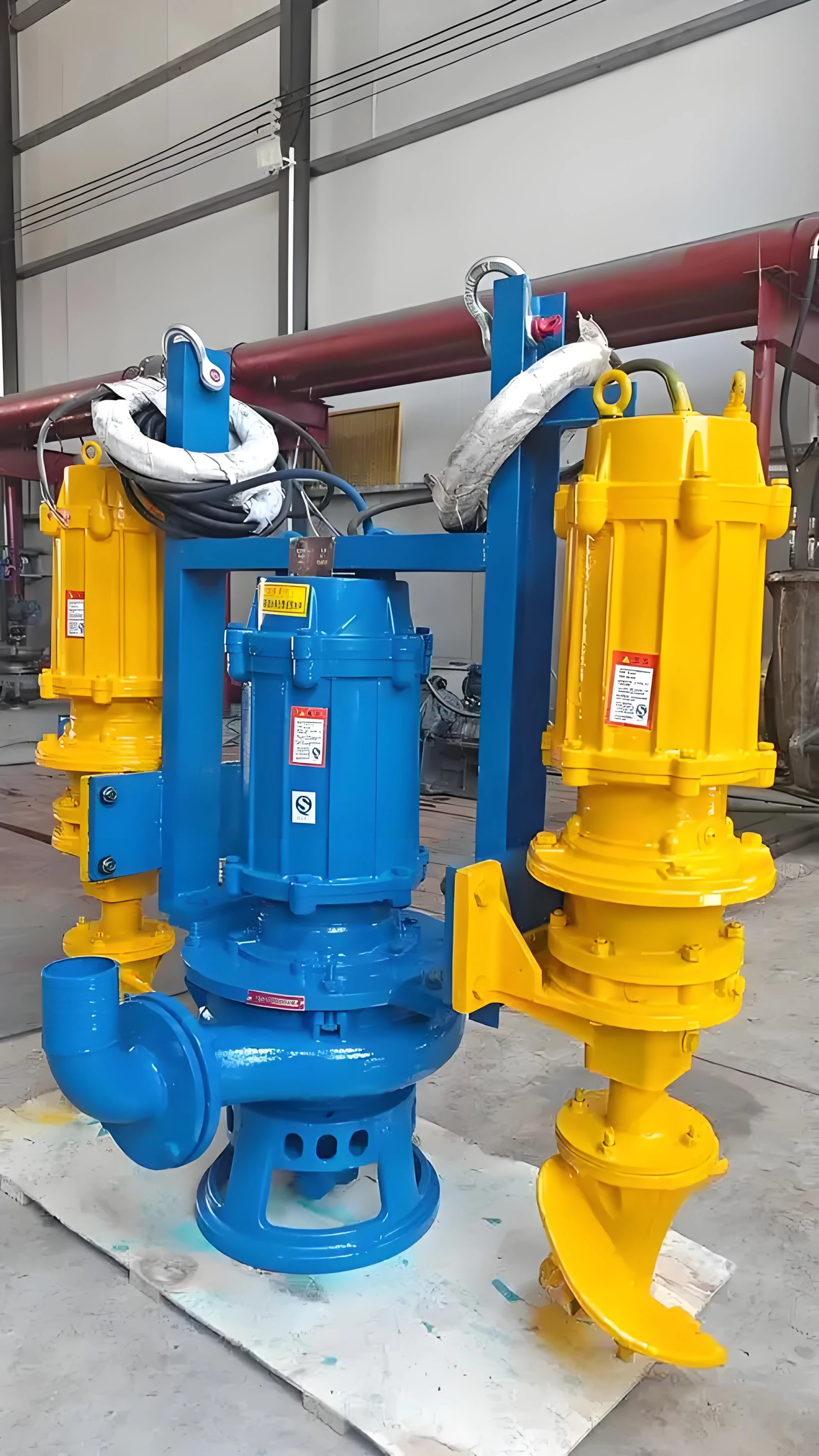
Auxiliary Slurry Pump Manufacturing Specification and Performance Analysis
In the industrial hierarchy of fluid dynamics, the auxiliary slurry pump serves as a critical secondary stage or supporting unit within larger slurry transport systems, commonly found in mineral processing, chemical refining, and wastewater treatment plants. Unlike primary pumps that handle the initial raw intake, auxiliary slurry pumps are engineered to manage specific flow redirections, recirculation loops, or pressure stabilization for downstream processing. The technical position of these pumps is defined by their ability to maintain a constant volumetric flow rate while transporting non-Newtonian fluids containing high concentrations of abrasive solid particulates. Core performance is measured by the pump's capacity to mitigate internal erosion, manage variable viscosity, and operate under high-pressure differentials without compromising the structural integrity of the impeller or the casing.
Material Science & Manufacturing
The engineering of an auxiliary slurry pump begins with advanced material science to combat the dual threats of abrasive wear and chemical corrosion. High-chrome white irons ( ASTM A532) are typically employed for the impeller and liner, utilizing a martensitic matrix with embedded primary carbides (M7C3) to ensure a hardness rating exceeding 60 HRC. For applications involving acidic or alkaline slurries, duplex stainless steels (e.g., CD4MCu) are utilized to provide a balance between tensile strength and pitting resistance.
The manufacturing process follows a stringent metallurgical sequence. Precision investment casting is utilized for the impeller to ensure a balanced hydrodynamic profile, reducing turbulence that would otherwise accelerate localized erosion. The casing undergoes a centrifugal casting process to ensure a dense, pore-free structure, followed by heat treatment (quenching and tempering) to homogenize the microstructure. Dimensional tolerances for the wear rings are maintained within microns to prevent internal recirculation, which significantly impacts the pump's volumetric efficiency. Furthermore, the shafting is typically manufactured from forged alloy steel, induction-hardened and coated with ceramic or tungsten carbide via High-Velocity Oxy-Fuel (HVOF) spraying to prevent shaft sleeve degradation at the seal interface.
Performance & Engineering
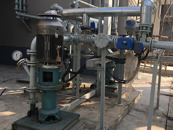
The engineering logic of an auxiliary slurry pump centers on the management of "Critical Solids Velocity" (CSV). To prevent the settling of particulates within the pump casing—which would lead to clogging and catastrophic vibration—the flow velocity must be maintained above the settling velocity of the largest particle in the slurry. This requires precise impeller vane geometry and the application of the Affinity Laws to match the motor's RPM with the required head and flow rate.
Force analysis indicates that the primary stress points are located at the impeller eye and the volute tongue. To mitigate this, engineers implement a "sacrificial liner" design, where replaceable wear plates absorb the kinetic energy of the slurry, protecting the main pump housing. Environmental resistance is addressed through the implementation of mechanical seals with external flushing systems (API Plan 32 or 54), which prevent abrasive particles from entering the seal faces. Compliance with international hydraulic standards ensures that the Net Positive Suction Head required (NPSHr) is kept significantly lower than the Net Positive Suction Head available (NPSHa) to eliminate cavitation, which would otherwise cause rapid material pitting and structural fatigue.
Technical Specifications
| Parameter Dimension | Standard Alloy Grade | High-Chrome Grade | Duplex Stainless Grade | Ceramic Lined Grade |
|---|---|---|---|---|
| Hardness (Rockwell C) | 25 - 35 HRC | 60 - 65 HRC | 30 - 40 HRC | > 70 HRC |
| Max Particle Size (mm) | < 5 mm | 10 - 25 mm | 5 - 12 mm | < 3 mm |
| Corrosion Rate (mm/year) | 0.5 - 1.2 | 0.2 - 0.8 | 0.05 - 0.2 | < 0.01 |
| Max Operating Pressure (MPa) | 1.6 | 2.5 | 2.0 | 1.2 |
| Efficiency Range (%) | 65% - 75% | 60% - 72% | 62% - 74% | 58% - 68% |
| Typical Service Life (Hrs) | 2,000 - 4,000 | 8,000 - 12,000 | 6,000 - 10,000 | 15,000+ |
Failure Mode & Maintenance
Failure analysis in auxiliary slurry pumps generally falls into three categories: erosive wear, cavitation damage, and seal failure. Erosive wear manifests as "thinning" of the volute liner and impeller vanes, typically occurring at high-velocity impact zones. This is diagnosed through ultrasonic thickness testing during scheduled shutdowns. Cavitation is identified by a characteristic "gravel-like" noise and the presence of small, honeycomb-like pits on the impeller suction side, caused by the collapse of vapor bubbles during pressure recovery.
Maintenance protocols must be predictive rather than reactive. A professional maintenance regimen includes: 1) Quarterly vibration analysis to detect misalignment or bearing fatigue; 2) Periodic checking of the gap between the impeller and the suction liner to maintain volumetric efficiency; 3) Monitoring of the seal flush water pressure to ensure no slurry ingress; and 4) Dynamic balancing of the impeller after any welding repairs to prevent shaft deflection. For severe erosion, the application of cold-spray metal deposition or ceramic cladding is recommended to restore original dimensions without introducing heat-affected zones (HAZ) that could compromise the base metal's tempering.
Industry FAQ
Q: How do we determine the optimal material choice between High-Chrome iron and Duplex Stainless Steel for our auxiliary pump?
A: The decision is based on the ratio of abrasion to corrosion. If the slurry is predominantly abrasive with low chemical activity, High-Chrome iron (ASTM A532) is superior due to its hardness. However, if the slurry contains chlorides or acids that cause chemical pitting, Duplex Stainless Steel is required, as chrome carbides can be selectively attacked by corrosive agents, leading to "grain shedding."
Q: What is the impact of slurry density fluctuations on the pump's NPSH requirements?
A: Increased slurry density elevates the fluid's viscosity and changes the vapor pressure characteristics. This typically increases the NPSHr (Net Positive Suction Head required). If the density increases beyond the design limit without a corresponding increase in suction head, the pump will cavitate, leading to rapid degradation of the impeller eye.
Q: Why are we seeing premature failure in the mechanical seals despite using silicon carbide faces?
A: This is often caused by "particle wedging," where fine abrasive particles bypass the flush system and lodge between the seal faces. This transforms the sliding friction into an abrasive grinding action. The solution is to implement a pressurized API Plan 32 flush to create a positive pressure barrier, ensuring no slurry enters the seal chamber.
Q: Can the impeller be repaired via welding, or must it be replaced entirely?
A: Welding is possible but risky. The heat from welding can create a brittle heat-affected zone (HAZ) in high-chrome materials, leading to stress cracking. If welding is performed, a strict pre-heating and post-weld heat treatment (PWHT) cycle must be followed, and the impeller must be re-balanced to ISO 1940 G2.5 standards.
Q: How does the "critical solids velocity" affect the selection of the pump's diameter?
A: The pump diameter must be sized to ensure the flow velocity remains above the CSV to prevent sedimentation. If the diameter is too large, the velocity drops, causing solids to settle in the volute, which leads to unbalanced radial forces and premature bearing failure. Conversely, too small a diameter increases the fluid velocity excessively, accelerating erosive wear.
Conclusion
The operational efficiency of an auxiliary slurry pump is fundamentally dependent on the synergy between material hardness, hydraulic geometry, and rigorous maintenance protocols. By prioritizing the use of high-chrome alloys and adhering to critical solids velocity calculations, industrial operators can significantly reduce downtime and extend the mean time between failures (MTBF) in abrasive environments.
Looking forward, the integration of smart sensing—such as real-time erosion monitoring and AI-driven vibration analysis—will transform auxiliary slurry pump management from a scheduled task to a condition-based strategy. This technical evolution will ensure higher systemic reliability and lower total cost of ownership (TCO) for high-intensity industrial processing plants.
-
1 2 hp sewage ejector pump Performance Engineering
News2026-05-25
-
Zoeller 1/2 hp sewage pump Performance Analysis
News2026-05-25
-
Effluent Pump Performance Analysis
News2026-05-25
-
sump pump vs effluent pump Performance Analysis
News2026-05-25
-
sewer pumps residential Performance Analysis
News2026-05-25
-
Sewage Pump Company Performance and Engineering
News2026-05-24
-
sewage pump 1/2 hp Performance Analysis
News2026-05-24
-
Sewage Ejector Systems Performance Analysis
News2026-05-24
-
Sewage Ejection System Material Science and Manufacturing
News2026-05-24
-
sewage and effluent pumps Performance Engineering
News2026-05-24
-
pump for sewage water Performance Analysis
News2026-05-23
-
plumbing sewage ejector pump Performance Engineering
News2026-05-23
-
home sewer pump station Performance and Engineering
News2026-05-23
-
high pressure sump pump Performance Analysis
News2026-05-23
-
high head effluent pump Performance Analysis
News2026-05-23