English
- Afrikaans
- Albanian
- Amharic
- Arabic
- Armenian
- Azerbaijani
- Basque
- Belarusian
- Bengali
- Bosnian
- Bulgarian
- Catalan
- Cebuano
- Corsican
- Croatian
- Czech
- Danish
- Dutch
- English
- Esperanto
- Estonian
- Finnish
- French
- Frisian
- Galician
- Georgian
- German
- Greek
- Gujarati
- Haitian Creole
- hausa
- hawaiian
- Hebrew
- Hindi
- Miao
- Hungarian
- Icelandic
- igbo
- Indonesian
- irish
- Italian
- Japanese
- Javanese
- Kannada
- kazakh
- Khmer
- Rwandese
- Korean
- Kurdish
- Kyrgyz
- Lao
- Latin
- Latvian
- Lithuanian
- Luxembourgish
- Macedonian
- Malgashi
- Malay
- Malayalam
- Maltese
- Maori
- Marathi
- Mongolian
- Myanmar
- Nepali
- Norwegian
- Norwegian
- Occitan
- Pashto
- Persian
- Polish
- Portuguese
- Punjabi
- Romanian
- Russian
- Samoan
- Scottish Gaelic
- Serbian
- Sesotho
- Shona
- Sindhi
- Sinhala
- Slovak
- Slovenian
- Somali
- Spanish
- Sundanese
- Swahili
- Swedish
- Tagalog
- Tajik
- Tamil
- Tatar
- Telugu
- Thai
- Turkish
- Turkmen
- Ukrainian
- Urdu
- Uighur
- Uzbek
- Vietnamese
- Welsh
- Bantu
- Yiddish
- Yoruba
- Zulu
 Co., Ltd.")
Telephone: +86 13120555503
Email: frank@cypump.com


Apr . 01, 2024 17:55 Back to list
12 inch slurry pump Manufacturing Specification and Performance Analysis
12 Inch Slurry Pump Manufacturing Specification and Performance Analysis
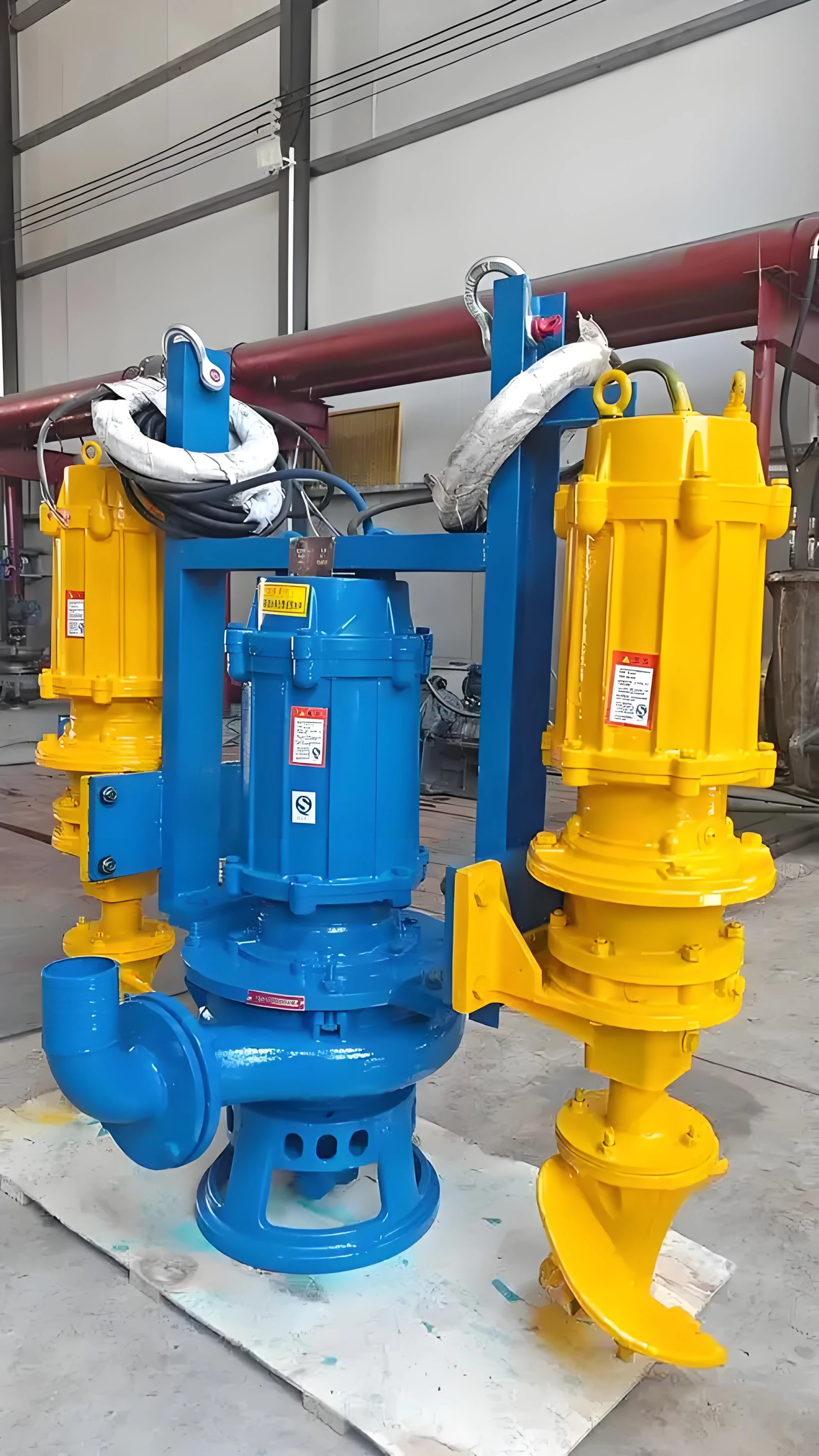
The 12 inch slurry pump represents a critical piece of heavy-duty industrial infrastructure designed for the transport of high-density, abrasive fluid mixtures. Positioned at the nexus of mineral processing, dredging, and waste management, these pumps are engineered to handle large volumes of solids-laden liquids—ranging from mine tailings and crushed ore to municipal sludge. Within the industrial value chain, the 12 inch designation refers to the discharge diameter, indicating a high-capacity system capable of managing substantial volumetric flow rates while resisting the extreme erosive forces inherent in slurry transport. The core technical challenge of these systems lies in balancing hydraulic efficiency with the structural integrity required to withstand continuous abrasive wear, necessitating advanced material science and precision engineering of the impeller and volute geometry.
Material Science & Manufacturing
The manufacturing of a 12 inch slurry pump is a rigorous exercise in metallurgical engineering, as the equipment must combat both erosive wear (mechanical removal of material by particles) and corrosive attack (chemical degradation). The selection of raw materials is dictated by the specific gravity and hardness of the slurry solids.
High-Chrome Alloys: For applications involving high-impact abrasion, Cr27 or Cr50 high-chromium white irons are utilized. These materials feature a microstructure of hard M7C3 carbides embedded in a martensitic matrix, providing a hardness typically exceeding 60 HRC. This ensures that the pump casing and impeller can withstand the scouring effect of quartz or hematite particles.
Natural Rubber Linings: In scenarios involving finer particles or highly acidic slurries, natural rubber (NR) or synthetic elastomers are used as liners. The elastic properties of rubber allow it to absorb the kinetic energy of impacting particles, causing the particle to rebound rather than gouging the substrate. The bonding process involves high-pressure vulcanization to ensure the liner remains adhered to the cast iron shell under extreme vacuum and pressure fluctuations.
Manufacturing Process Control: The production involves precision investment casting for the impeller to ensure dynamic balance and minimize turbulence. The volute is typically cast using sand-casting methods followed by CNC machining of the flange faces to ensure airtight seals. Key parameter control focuses on the "clearance gap" between the impeller and the wear plate; excessive gaps lead to recirculation and accelerated wear, while insufficient gaps risk catastrophic failure during the passage of oversized solids.
Performance & Engineering
Engineering a 12 inch slurry pump requires a complex analysis of fluid dynamics and force distribution. The primary objective is to maintain a "critical carrying velocity"—the minimum speed required to keep solids suspended in the fluid to prevent sedimentation and pipeline blockage.
Hydraulic Force Analysis: The pump must overcome the static head and the frictional head losses caused by the slurry's apparent viscosity. Engineers utilize the Darcy-Weisbach equation modified for slurry flow to calculate pressure drops. The impeller design employs a semi-open or closed configuration depending on the particle size distribution; semi-open impellers reduce the risk of clogging but slightly lower the total dynamic head (TDH).
Environmental Resistance & Sealing: To prevent the abrasive slurry from entering the bearing housing, advanced sealing mechanisms are employed. This typically includes an expeller (mechanical seal) that creates a centrifugal barrier, diverting the slurry away from the shaft seal. Additionally, gland water sealing systems provide a positive pressure barrier, ensuring that any leakage moves from the clean water side to the slurry side, protecting the mechanical integrity of the shaft.
Compliance and Safety: Structural engineering must account for the massive weight of the fluid-filled pump. The frame is constructed from heavy-duty fabricated steel to dampen vibrations and prevent resonance that could lead to fatigue failure of the coupling or shaft.
Technical Specifications
| Parameter Dimension | Standard Specification | High-Performance Range | Industrial Tolerance |
|---|---|---|---|
| Discharge Diameter | 300 mm (12 inch) | 300 mm (12 inch) | ± 0.5 mm |
| Max Flow Rate | 5,000 - 12,000 m³/h | Up to 15,000 m³/h | ± 5% Flow Deviation |
| Total Dynamic Head (TDH) | 20 - 80 meters | Up to 120 meters | ± 2% Pressure Variance |
| Max Particle Size | 80 - 120 mm | Up to 150 mm | Strict Limit per Design |
| Liner Material | High Chrome (A05) / Rubber | Ceramic Composite / SiC | Hardness > 60 HRC (Chrome) |
| Operating Speed | 600 - 1,200 RPM | Variable (VFD Controlled) | ± 10 RPM Stability |
Failure Mode & Maintenance
Despite robust engineering, 12 inch slurry pumps operate in some of the harshest environments on earth. Understanding the failure modes is essential for maximizing Mean Time Between Failures (MTBF).
Erosive Wear and Cavitation: The most common failure mode is the thinning of the volute liner and impeller vanes. Cavitation occurs when the Net Positive Suction Head Available (NPSHa) falls below the Required (NPSHr), creating vapor bubbles that implode and pit the metal surface. This is often exacerbated by operating the pump too far to the right of the Best Efficiency Point (BEP).
Fatigue Cracking and Vibration: Large-scale slurry pumps are susceptible to mechanical vibration caused by impeller imbalance (due to uneven wear) or misalignment with the motor. This leads to fatigue cracking in the pump shaft or the bearing housing, potentially resulting in sudden catastrophic shaft shear.
Seal Failure and Leakage: The failure of the gland water system often leads to the ingress of slurry into the bearing assembly. Once abrasive particles enter the lubrication oil, they act as grinding media, rapidly destroying the bearings and causing overheating.
Maintenance Protocol: Professional maintenance involves a scheduled regime of ultrasonic thickness testing (UT) on the liners to monitor wear rates. Impellers should be dynamically balanced during every overhaul. The lubrication system must be monitored for particle contamination using oil analysis techniques to detect early bearing wear.
Industry FAQ
Q: How do we determine whether to use high-chrome or rubber liners for a 12 inch pump?
A: The decision is based on the particle size and hardness. High-chrome alloys are superior for large, sharp, and hard particles (e.g., crushed rock) that cause high-impact abrasion. Rubber liners are preferred for fine, sandy slurries or corrosive chemicals where the material can "absorb" the impact of smaller particles without gouging.
Q: What is the impact of increasing the pump speed via VFD on the wear rate?
A: Wear rates in slurry pumps typically increase exponentially with velocity (often proportional to the cube of the velocity). While a Variable Frequency Drive (VFD) allows for flow optimization, running the pump at excessive speeds significantly accelerates the erosion of the impeller and volute, reducing the service life of the wear parts.
Q: Why is the pump experiencing excessive vibration despite being new?
A: Common causes include misalignment between the pump and the motor, an improperly secured baseplate, or "slugging," where inconsistent slurry density creates erratic hydraulic loads. We recommend a laser alignment check and a verification of the slurry concentration at the suction inlet.
Q: How can we prevent cavitation in high-capacity 12 inch installations?
A: To prevent cavitation, ensure the suction piping is as short and straight as possible to minimize friction loss. Increasing the static head (raising the source tank) or reducing the fluid temperature to lower vapor pressure are also effective engineering solutions.
Q: What is the significance of the "critical carrying velocity" in slurry transport?
A: If the flow velocity drops below the critical carrying velocity, the heavy solids will settle at the bottom of the pipe (stratification). This not only increases the risk of total blockage but also causes "localized wear" at the bottom of the pipe and pump volute, leading to premature failure.
Conclusion
The 12 inch slurry pump is a sophisticated engineering solution designed to manage the volatile intersection of high-volume hydraulics and extreme material abrasion. Its operational success depends not only on the initial selection of high-chrome alloys or rubber elastomers but also on the precise calibration of flow velocities and the rigorous management of the Net Positive Suction Head. By integrating advanced material science with a deep understanding of fluid dynamics, operators can ensure these systems maintain peak efficiency in the most demanding industrial environments.
Looking forward, the industry is shifting toward "intelligent pumping," incorporating real-time wear sensors and AI-driven predictive maintenance to replace scheduled overhauls with condition-based interventions. For procurement and engineering teams, the priority must remain on the synergy between the pump's metallurgical specifications and the specific chemical and physical properties of the transported medium to maximize the total cost of ownership (TCO) and operational uptime.
-
Effluent vs Sump Pump Performance Analysis
News2026-05-22
-
effluent septic pump Performance Engineering
News2026-05-22
-
best sewer pumps Performance Engineering
News2026-05-22
-
best sewer pump Performance Analysis
News2026-05-22
-
best sewage pumps Performance Engineering
News2026-05-22
-
basement bathroom sewage pump Material Science Manufacturing
News2026-05-21
-
wastewater treatment plant pumps Material Science Manufacturing
News2026-05-21
-
waste water pump for basement Material Science Manufacturing
News2026-05-21
-
sump pump sewage Performance Analysis
News2026-05-21
-
sump pump for sewage Material Science and Manufacturing
News2026-05-21
-
sump pump for septic systems Material Science Manufacturing
News2026-05-20
-
sump pump and ejector pump Material Science Manufacturing
News2026-05-20
-
sewage treatment plant pumps Performance Analysis
News2026-05-20
-
sewage tank pump Material Science and Manufacturing
News2026-05-20
-
sewage pump for septic tank Performance Analysis
News2026-05-20


