English
- Afrikaans
- Albanian
- Amharic
- Arabic
- Armenian
- Azerbaijani
- Basque
- Belarusian
- Bengali
- Bosnian
- Bulgarian
- Catalan
- Cebuano
- Corsican
- Croatian
- Czech
- Danish
- Dutch
- English
- Esperanto
- Estonian
- Finnish
- French
- Frisian
- Galician
- Georgian
- German
- Greek
- Gujarati
- Haitian Creole
- hausa
- hawaiian
- Hebrew
- Hindi
- Miao
- Hungarian
- Icelandic
- igbo
- Indonesian
- irish
- Italian
- Japanese
- Javanese
- Kannada
- kazakh
- Khmer
- Rwandese
- Korean
- Kurdish
- Kyrgyz
- Lao
- Latin
- Latvian
- Lithuanian
- Luxembourgish
- Macedonian
- Malgashi
- Malay
- Malayalam
- Maltese
- Maori
- Marathi
- Mongolian
- Myanmar
- Nepali
- Norwegian
- Norwegian
- Occitan
- Pashto
- Persian
- Polish
- Portuguese
- Punjabi
- Romanian
- Russian
- Samoan
- Scottish Gaelic
- Serbian
- Sesotho
- Shona
- Sindhi
- Sinhala
- Slovak
- Slovenian
- Somali
- Spanish
- Sundanese
- Swahili
- Swedish
- Tagalog
- Tajik
- Tamil
- Tatar
- Telugu
- Thai
- Turkish
- Turkmen
- Ukrainian
- Urdu
- Uighur
- Uzbek
- Vietnamese
- Welsh
- Bantu
- Yiddish
- Yoruba
- Zulu
 Co., Ltd.")
Telephone: +86 13120555503
Email: frank@cypump.com


Apr . 01, 2024 17:55 Back to list
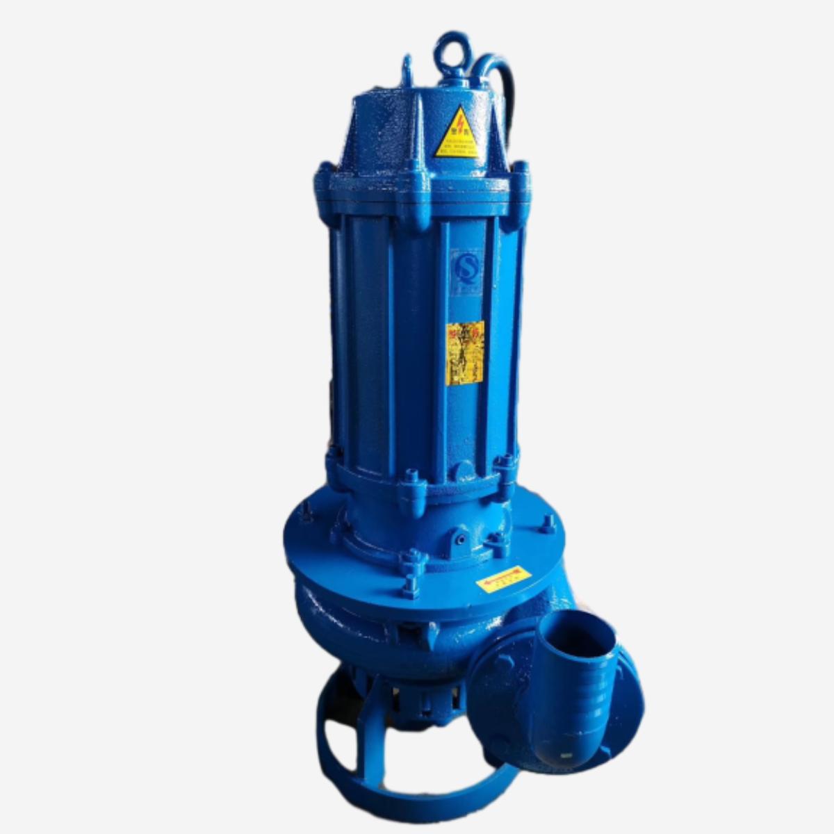
submersible effluent pump Performance Analysis
Introduction
Submersible effluent pumps are centrifugal pumps specifically designed for the removal of wastewater and sewage from residential, commercial, and industrial applications. Positioned within the effluent tank or basin, these pumps operate submerged in the liquid, offering significant advantages over surface-mounted systems, including reduced noise, elimination of priming issues, and improved efficiency. Their technical position in the wastewater treatment chain is crucial, functioning as the primary mechanism for conveying effluent from septic tanks, lift stations, and other wastewater holding areas to subsequent treatment or disposal sites. Core performance characteristics revolve around flow rate (gallons per minute or liters per second), head (vertical distance the pump can lift the effluent), motor horsepower, solids handling capability (typically measured in sphere diameter), and overall pump efficiency. A key industry pain point is balancing the need for high flow rates and heads with the imperative to minimize energy consumption and ensure long-term reliability in abrasive and corrosive environments.
Material Science & Manufacturing
The construction of a submersible effluent pump necessitates careful material selection to withstand the harsh operating environment. Pump housings are commonly manufactured from high-density polyethylene (HDPE) for its excellent chemical resistance, impact strength, and cost-effectiveness. Alternatively, cast iron (specifically ductile iron ASTM A536-83) is used for increased durability and resistance to abrasive wear, often with an epoxy coating to enhance corrosion protection. Impellers are frequently constructed from engineered thermoplastics like polypropylene or similar materials exhibiting high wear resistance, or stainless steel (304 or 316) for applications requiring greater strength and resistance to aggressive chemicals. Shafts are typically made of 4140 alloy steel, heat treated to achieve a Rockwell C hardness of 58-62 for optimal tensile strength and resistance to torsional stress. The manufacturing process involves several key steps. The HDPE housings are typically produced via rotational molding, ensuring uniform wall thickness and stress-free construction. Cast iron housings undergo sand casting, followed by machining and coating. Impellers are injection molded or, in the case of stainless steel, precision cast and machined. Motor housings require specialized sealing processes to prevent water ingress. Parameter control is critical: HDPE resin melt temperature during rotational molding, casting temperature and cooling rate for cast iron, impeller blade geometry and balance, and the quality of epoxy coatings all significantly impact pump performance and longevity. Wire insulation must meet or exceed Class H standards for high-temperature resistance.
Performance & Engineering
Performance engineering centers on hydraulic design and motor selection. The pump's impeller and volute casing are designed based on computational fluid dynamics (CFD) analysis to optimize flow characteristics, minimize turbulence, and maximize hydraulic efficiency. The impeller geometry (blade angle, number of blades, and blade profile) dictates the pump’s head-flow curve. Force analysis is crucial, particularly regarding the radial and axial thrust loads imposed on the motor shaft by the impeller. Bearings are selected (typically deep-groove ball bearings or roller bearings) to withstand these loads and ensure smooth, reliable operation. Environmental resistance is addressed through robust sealing systems. Double mechanical seals (silicon carbide vs. silicon carbide) with an oil-filled barrier are commonly employed to prevent effluent leakage and protect the motor. Compliance requirements are dictated by regional regulations, including energy efficiency standards (e.g., US EPA’s Energy Star program) and safety certifications (e.g., UL and CSA). The pump’s electrical system must conform to applicable electrical codes (NEC, IEC). Furthermore, considerations for solids handling capabilities are paramount, with pump designs incorporating open impellers or vortex impellers to prevent clogging from rags, debris, and other solid materials. Thermal overload protection within the motor is essential to prevent overheating and premature failure.
Technical Specifications
| Parameter | Unit | Typical Range (Residential) | Typical Range (Commercial/Industrial) |
|---|---|---|---|
| Flow Rate | GPM (Gallons per Minute) | 25-75 | 100-500 |
| Head | ft (feet) | 10-30 | 30-100 |
| Motor Horsepower | HP | 1/2 - 1 | 1 - 5 |
| Solids Handling | in (inches) | 1/2 – 1 | 1 – 2.5 |
| Voltage | V (Volts) | 115/230 | 230/460/575 |
| Phase | Single | Single or Three |
Failure Mode & Maintenance
Submersible effluent pumps are susceptible to several failure modes. Fatigue cracking in the impeller or housing can occur due to cyclical loading and stress concentration, particularly in areas around bolt holes or sharp corners. Delamination of epoxy coatings on cast iron housings exposes the metal to corrosion. Degradation of rubber components (seals, check valves) due to chemical attack or prolonged immersion in effluent leads to leakage and reduced pump efficiency. Oxidation of electrical connections causes increased resistance and potential motor failure. Solids build-up within the impeller or volute casing restricts flow and overloads the motor. Bearing failure results from inadequate lubrication, contamination, or excessive loading. Maintenance solutions involve regular inspections for wear and corrosion, periodic cleaning to remove debris, and replacement of worn seals and bearings. Proper grounding is critical to prevent electrical shock and corrosion. Motor windings should be tested for insulation resistance periodically. When replacing components, it's imperative to use manufacturer-approved parts. Preventive maintenance schedules should be tailored to the specific application and operating conditions. Monitoring pump performance (flow rate, current draw) can provide early warnings of potential issues. Correct installation, ensuring proper alignment and minimizing stress on the discharge piping, is vital for prolonged service life.
Industry FAQ
Q: What is the significance of the pump's power curve, and how does it impact system design?
A: The pump’s power curve (head-flow curve) illustrates the relationship between the pump's head and flow rate. It is fundamental to system design because it dictates the pump’s operating point within the system. The designer must select a pump whose power curve intersects the system curve (representing the friction losses in the piping) at a point that satisfies the required flow rate and head. A poorly matched pump can result in inefficient operation, cavitation, or pump failure.
Q: How do I determine the correct pump size for my application?
A: Determining the correct pump size requires calculating the total dynamic head (TDH) and the required flow rate. TDH includes static lift, friction losses in the piping, and any pressure at the discharge point. Flow rate is determined by the wastewater generation rate. Use pump selection software or consult with a pump engineer to ensure proper sizing. Oversizing the pump can lead to increased energy consumption and premature wear.
Q: What are the common causes of pump overheating, and how can they be addressed?
A: Common causes of pump overheating include insufficient flow (due to blockage or low wastewater level), excessive cycling (short cycling), voltage imbalances, and motor winding insulation failure. Address blockages, ensure adequate wastewater level, verify proper voltage, and test the motor windings. Thermal overload protection should trip the pump if overheating occurs.
Q: What are the best practices for extending the life of a submersible effluent pump?
A: Regular maintenance is key. Inspect seals and bearings, clean the impeller and volute casing, ensure proper grounding, and monitor pump performance. Avoid running the pump dry, protect it from freezing temperatures, and use manufacturer-approved replacement parts. Implement a preventative maintenance schedule tailored to your application.
Q: How does the material of the pump housing affect its lifespan and performance?
A: The pump housing material dictates its resistance to corrosion, abrasion, and impact damage. HDPE is cost-effective and chemically resistant but has lower strength than cast iron. Cast iron offers higher durability and abrasion resistance, particularly when epoxy coated. Choosing the appropriate material depends on the specific chemical composition of the effluent and the level of abrasive solids present.
Conclusion
Submersible effluent pumps represent a critical component in wastewater management systems, providing reliable and efficient removal of effluent. Successful implementation relies on a thorough understanding of material science, hydraulic principles, and electrical safety standards. The selection process must consider factors such as flow rate, head, solids handling capability, and the chemical composition of the effluent.
Ongoing preventative maintenance, combined with diligent monitoring of pump performance, is essential for maximizing lifespan and minimizing downtime. Advancements in pump design, including the integration of variable frequency drives (VFDs) for energy efficiency and smart monitoring systems for predictive maintenance, are shaping the future of this critical technology.
-
Comprehensive Guide to Waterproof ORings for Optimal Sealing Solutions
News2026-06-09
-
basement bathroom pump systems Performance Analysis
News2026-06-24
-
basement bathroom ejector pump system Performance Engineering
News2026-06-24
-
2 hp sewage pump Performance Engineering
News2026-06-24
-
1 hp septic pump Performance Engineering
News2026-06-24
-
submersible effluent pump Performance Analysis
News2026-06-24
-
submergable pump Material Science
News2026-06-23
-
sewer injection pump Performance Engineering
News2026-06-23
-
Sewer Ejector Pump System Performance Analysis
News2026-06-23
-
septic tank pump for sale Performance Engineering
News2026-06-23
-
septic pump for sale Performance Engineering
News2026-06-23
-
septic ejector system Performance Analysis
News2026-06-22
-
replace septic pump Performance Analysis
News2026-06-22
-
pump system septic tank Performance Analysis
News2026-06-22
-
lift pump for sewer Performance and Engineering
News2026-06-22


