English
- Afrikaans
- Albanian
- Amharic
- Arabic
- Armenian
- Azerbaijani
- Basque
- Belarusian
- Bengali
- Bosnian
- Bulgarian
- Catalan
- Cebuano
- Corsican
- Croatian
- Czech
- Danish
- Dutch
- English
- Esperanto
- Estonian
- Finnish
- French
- Frisian
- Galician
- Georgian
- German
- Greek
- Gujarati
- Haitian Creole
- hausa
- hawaiian
- Hebrew
- Hindi
- Miao
- Hungarian
- Icelandic
- igbo
- Indonesian
- irish
- Italian
- Japanese
- Javanese
- Kannada
- kazakh
- Khmer
- Rwandese
- Korean
- Kurdish
- Kyrgyz
- Lao
- Latin
- Latvian
- Lithuanian
- Luxembourgish
- Macedonian
- Malgashi
- Malay
- Malayalam
- Maltese
- Maori
- Marathi
- Mongolian
- Myanmar
- Nepali
- Norwegian
- Norwegian
- Occitan
- Pashto
- Persian
- Polish
- Portuguese
- Punjabi
- Romanian
- Russian
- Samoan
- Scottish Gaelic
- Serbian
- Sesotho
- Shona
- Sindhi
- Sinhala
- Slovak
- Slovenian
- Somali
- Spanish
- Sundanese
- Swahili
- Swedish
- Tagalog
- Tajik
- Tamil
- Tatar
- Telugu
- Thai
- Turkish
- Turkmen
- Ukrainian
- Urdu
- Uighur
- Uzbek
- Vietnamese
- Welsh
- Bantu
- Yiddish
- Yoruba
- Zulu

Telephone: +86 13120555503
Email: frank@cypump.com


Apr . 01, 2024 17:55 Back to list
effluent pump for septic tank Material Science Manufacturing
Introduction
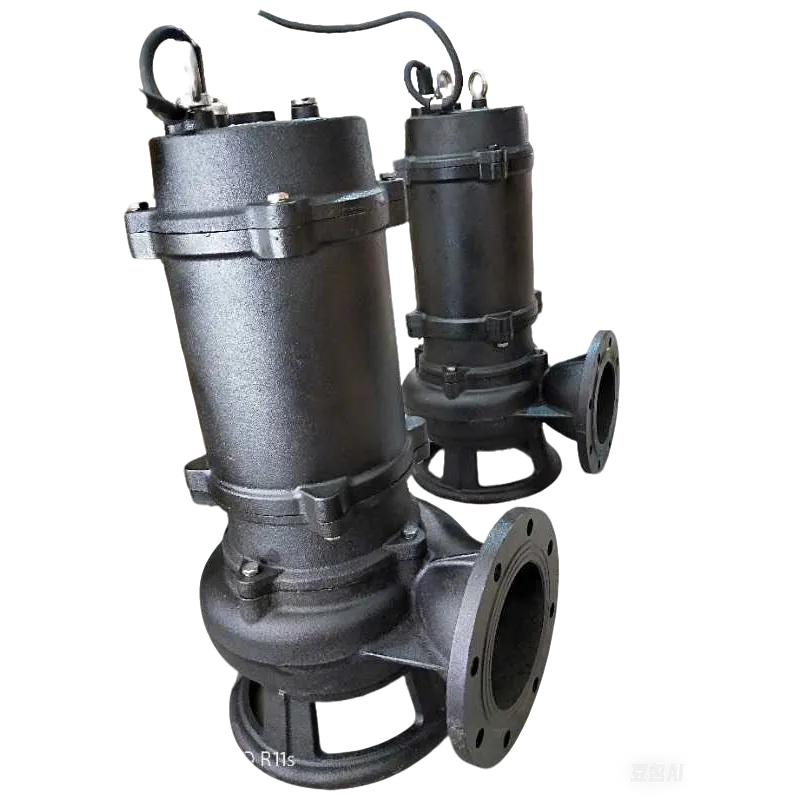
Effluent pumps for septic tanks represent a critical component in decentralized wastewater treatment systems. These submersible pumps are specifically designed to transfer pre-treated wastewater, or effluent, from the septic tank to a subsequent treatment stage – typically a drainfield, leach field, or mound system. Positioned within the tank, these pumps overcome elevation differences and ensure consistent hydraulic pressure for effective effluent dispersal. Unlike general-purpose pumps, effluent pumps must handle solids-laden wastewater, resist corrosion from aggressive septic tank environments, and operate reliably with minimal maintenance. Core performance characteristics include flow rate (gallons per minute/liters per minute), total dynamic head (TDH – the vertical distance the pump can lift the liquid plus friction losses in the piping), and solids handling capability (expressed as maximum sphere size in millimeters or inches). A critical pain point in the industry revolves around pump failure leading to septic system backups, environmental contamination, and costly repairs. Selection hinges on accurate sizing to match the drainfield’s absorption capacity and the specific characteristics of the wastewater generated.
Material Science & Manufacturing
The construction of effluent pumps prioritizes materials resistant to the harsh chemical environment within a septic tank. Impellers and pump housings are commonly manufactured from engineered thermoplastics like polypropylene (PP) or polyvinyl chloride (PVC), chosen for their resistance to hydrogen sulfide (H₂S), sulfates, and organic acids generated during anaerobic digestion. However, for demanding applications and higher flow rates, cast iron with an epoxy coating is employed for enhanced durability and structural integrity. Shafts are typically made from stainless steel (304 or 316 grades) to prevent corrosion. Seals are crucial and typically utilize nitrile rubber, Viton (fluoroelastomer), or silicon carbide mechanical seals to maintain watertight integrity and prevent wastewater ingress into the motor. Manufacturing processes include injection molding for thermoplastic components, sand casting followed by epoxy coating for cast iron housings, and precision machining for shafts and impellers. Critical parameter control during manufacturing includes dimensional accuracy of impeller vanes (to maximize hydraulic efficiency), concentricity of the shaft within the housing (to minimize vibration and bearing wear), and consistent seal compression (to prevent leakage). Welding procedures, if applicable for mounting brackets, require full penetration and appropriate corrosion-resistant filler metals. Quality control involves hydrostatic testing to verify pressure containment and dielectric strength testing to ensure electrical safety.
Performance & Engineering
Effluent pump performance is governed by hydraulic principles and motor characteristics. The pump’s impeller imparts kinetic energy to the wastewater, converting it into pressure energy. Force analysis involves calculating the radial and axial forces acting on the impeller and shaft, which directly influence bearing life and overall pump stability. Environmental resistance is paramount; pumps must operate reliably in continuously damp, often corrosive environments. This necessitates robust sealing systems and corrosion-resistant materials as previously detailed. Compliance requirements vary by jurisdiction but generally adhere to standards for electrical safety (UL/CSA certifications), hydraulic performance (flow rate and head curves), and solids handling capacity. Functional implementation hinges on proper pump sizing based on the drainfield’s percolation rate (the rate at which water is absorbed into the soil). Undersized pumps lead to system backups, while oversized pumps can cause premature drainfield failure due to hydraulic overload. Pump control systems often incorporate float switches or pressure transducers to automatically activate and deactivate the pump based on wastewater level within the septic tank, preventing dry-running and overflow. Furthermore, many systems include alarm systems to alert homeowners to pump malfunctions or high liquid levels.
Technical Specifications
| Parameter | Unit | Typical Range | Description |
|---|---|---|---|
| Flow Rate | GPM (Gallons Per Minute) | 20-100 | Volume of effluent pumped per minute. |
| Total Dynamic Head (TDH) | Feet | 10-50 | Maximum vertical distance the pump can lift effluent, including friction losses. |
| Horsepower (HP) | HP | 1/2 - 1 | Motor power output. |
| Solids Handling | Inches | Up to 2 | Maximum size of solid particles the pump can pass. |
| Voltage | Volts | 120/240 | Electrical voltage requirement. |
| Phase | - | Single/Three | Electrical phase requirement. |
Failure Mode & Maintenance
Effluent pump failures typically stem from several modes. Fatigue cracking can occur in the impeller due to continuous exposure to abrasive solids. Delamination of epoxy coatings on cast iron housings exposes the underlying metal to corrosion. Degradation of seals leads to leakage and motor damage. Oxidation of electrical connections causes intermittent operation or complete failure. Common failure points include the impeller, the motor winding, the float switch, and the pump housing. Preventative maintenance is crucial and involves regular inspection of the pump for signs of corrosion, wear, or leakage. Annual cleaning of the pump intake screen prevents clogging and maintains optimal flow. Lubrication of bearings (if applicable) extends their lifespan. Periodically testing the float switch ensures proper operation. In the event of failure, a thorough failure analysis should be conducted to identify the root cause. This might involve visual inspection, dimensional measurements, and material testing. Repair options include replacing worn components (impeller, seals, float switch) or replacing the entire pump. Proper pump storage during periods of inactivity is also important; ensure the pump remains protected from freezing temperatures and direct sunlight.
Industry FAQ
Q: What is the significance of the pump’s shut-off head in relation to drainfield performance?
A: The pump's shut-off head is the maximum head at which the pump can deliver any flow. It's vital because it needs to exceed the static head (vertical lift) plus the friction losses in the piping to ensure the effluent reaches the drainfield with sufficient pressure. If the pump’s shut-off head is too low, the effluent won't reach the drainfield, leading to backups.
Q: How does the impeller design influence the pump's efficiency and solids handling capability?
A: Impeller design is critical. A radial impeller is better for higher head and lower flow, while a mixed-flow impeller provides a balance between head and flow. Open impellers are more resistant to clogging by solids, while closed impellers are generally more efficient in clean liquids. Impeller vane geometry and number are optimized to maximize hydraulic efficiency and minimize wear.
Q: What are the implications of using a pump with a motor that is not thermally protected?
A: A thermally protected motor prevents overheating by automatically shutting off the pump if it exceeds its temperature limit. Without this protection, the motor can burn out, leading to pump failure and potentially a hazardous situation. Thermal protection is a critical safety feature.
Q: How important is the material compatibility between the pump components and the effluent composition?
A: Extremely important. Septic tank effluent contains corrosive substances like hydrogen sulfide, sulfates, and organic acids. Using incompatible materials (e.g., carbon steel without adequate coating) will result in rapid corrosion and pump failure. Engineered thermoplastics and corrosion-resistant alloys are essential.
Q: What factors should be considered when selecting a pump control system (e.g., float switch vs. pressure transducer)?
A: Float switches are simpler and more cost-effective but can be prone to mechanical failure and may not provide precise control. Pressure transducers offer more accurate level monitoring and control, allowing for variable pump speeds and optimized energy consumption, but are more complex and expensive.
Conclusion
Effluent pumps are integral to the reliable operation of septic tank systems, requiring careful consideration of material science, hydraulic performance, and long-term durability. The selection process demands a thorough understanding of the drainfield’s characteristics, effluent composition, and potential failure modes. Prioritizing corrosion resistance, solids handling capability, and appropriate motor protection are paramount for minimizing downtime and maximizing system lifespan.
Future advancements in effluent pump technology may focus on incorporating smart control systems with remote monitoring capabilities, variable frequency drives for energy efficiency, and self-cleaning impellers to reduce maintenance requirements. Continuous material research aiming for increased corrosion resistance and reduced weight will further enhance pump performance and longevity, contributing to more sustainable and cost-effective wastewater treatment solutions.
-
residential sewage pumps Material Science and Manufacturing
News2026-05-26
-
residential sewage lift pump Performance Analysis
News2026-05-26
-
high head sump pump Performance and Engineering
News2026-05-26
-
effluent pump for septic tank Material Science Manufacturing
News2026-05-26
-
effluent and sewage pumps Material Science Manufacturing
News2026-05-26
-
1 2 hp sewage ejector pump Performance Engineering
News2026-05-25
-
Zoeller 1/2 hp sewage pump Performance Analysis
News2026-05-25
-
Effluent Pump Performance Analysis
News2026-05-25
-
sump pump vs effluent pump Performance Analysis
News2026-05-25
-
sewer pumps residential Performance Analysis
News2026-05-25
-
Sewage Pump Company Performance and Engineering
News2026-05-24
-
sewage pump 1/2 hp Performance Analysis
News2026-05-24
-
Sewage Ejector Systems Performance Analysis
News2026-05-24
-
Sewage Ejection System Material Science and Manufacturing
News2026-05-24
-
sewage and effluent pumps Performance Engineering
News2026-05-24